background image

Menu

79


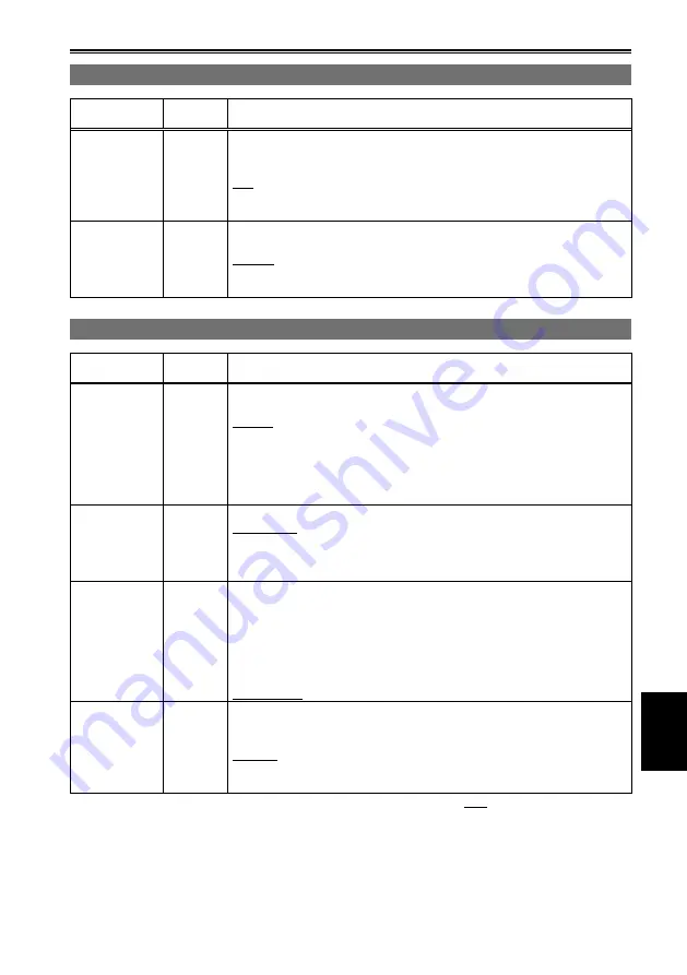
CAMERA SETUP screen (continued)

Item

Display 

mode

Description of settings

KNEE

(Camera)

To avoid overexposure, select the compression level (knee point) of the high 

intensity video signals received through MOS.

LOW:

  Low setting (Compression starts at approx. 80 %.)

MID

Medium setting (Compression starts at approx. 90 %.)

HIGH:

  High Setting (Compression starts at approx. 100 %.)

Not available when GAMMA is set to CINE-LIKE. 

MATRIX

(Camera)

Selects the MATRIX table suitable for the desired color expression during 

shooting.

NORM1

: Suitable for shooting in the open air or under a halogen lamp.

NORM2:

 Suitable for brighter colors than the NORM1 mode.

CINE-LIKE:

 Suitable for cinema-like image.

SW MODE screen

Item

Display 

mode

Description of settings

HANDLE 

ZOOM

(Camera)

Sets the zoom speed assigned to each setting position of the HANDLE ZOOM 

switch.

L/OFF/H:

  Sets LOW (low speed)/OFF/HIGH (high speed) to the 1//3 position. 

(Zoom is disabled when set to OFF.)

L/M/H:   

Sets LOW (low speed)/MID (medium speed)/HIGH (high speed) to 

the 1//3 position.

L/OFF/M:  

Sets LOW (low speed)/OFF/MID (medium speed) to the 1//3 

position. (Zoom is disabled when set to OFF.)

IRIS DIAL

(Camera)

Sets the rotation direction and the aperture control of the IRIS/CONV. dial.

DOWN OPEN: 

The iris opens when the IRIS/CONV. dial is turned downward.

UP OPEN: 

The iris opens when the IRIS/CONV. dial is turned upward.

This setting does not change the direction of the convergence point 

adjustment.

USER1

(Camera)

Selects the function assigned to the USER1 button.

INH

USER1 button is disabled. No function operates by pressing 

the USER1 button. 

R-IMAGE

The image from the right lens is displayed on the viewfinder 

and LCD monitor.

MIX

The images from the left and right lenses are superimposed 

and displayed on the viewfinder and LCD monitor. (Page 38)

SHOT MARK

:  Shot mark recording (Page 44)

USER2

(Camera)

Assigns a function to the USER button.

The setting contents are the same as USER1.

INH


R-IMAGE

MIX

SHOT MARK

        indicates the factory setting.

Summary of Contents for AG-3DA1E

Page 1: ...s Memory Card Camera Recorder Model No AG 3DA1P Model No AG 3DA1E SS0710AS1080 PS D Printed in Japan VQT2Z46 1 Before operating this product please read the instructions carefully and save this manual for future use ENGLISH This product is eligible for the AVCCAM 3 Year Warranty Repair Program For details see page 9 ...

Page 2: ... liquids and do not place any liquid containers on top of the equipment WARNING Always keep memory cards optional accessory or accessories screw spacer microphone holder screws microphone holder adapter INPUT terminal covers out of the reach of babies and small children CAUTION To reduce the risk of fire or electric shock and annoying interference use the recommended accessories only CAUTION Do no...

Page 3: ...ed and used in accordance with the instructions may cause harmful interference to radio communications However there is no guarantee that interference will not occur in a particular installation If this equipment does cause harmful interference to radio or television reception which can be determined by turning the equipment off and on the user is encouraged to try to correct the interference by o...

Page 4: ...onvenience receptacles and the point where they exit from the apparatus 11 Only use attachments accessories specified by the manufacturer 12 Use only with the cart stand tripod bracket or table specified by the manufacturer or sold with the apparatus When a cart is used use caution when moving the cart apparatus combination to avoid injury from tip over 13 Unplug this apparatus during lightning st...

Page 5: ...Camera Recorder The rating plate is on the underside of the viewfinder Battery Charger AC Adaptor The rating plate is on the underside of the Battery Charger and AC Adaptor Disconnect the AC mains plug from the AC mains socket when not in use CAUTION The mains plug of the power supply cord shall remain readily operable The AC receptacle mains socket outlet shall be installed near the equipment and...

Page 6: ...ntinued indicates safety information FOR U K ONLY This appliance is supplied with a moulded three pin mains plug for your safety and convenience A 5 amp fuse is fitted in this plug Should the fuse need to be replaced please ensure that the replacement fuse has a rating of 5 amps and that it is approved by ASTA or BSI to BS1362 Check for the ASTA mark or the BSI mark on the body of the fuse If the ...

Page 7: ...a screwdriver 2 Replace the fuse Fuse indicates safety information FOR U K ONLY This appliance is supplied with a moulded three pin mains plug for your safety and convenience A 5 amp fuse is fitted in this plug Should the fuse need to be replaced please ensure that the replacement fuse has a rating of 5 amps and that it is approved by ASTA or BSI to BS1362 Check for the ASTA mark or the BSI mark o...

Page 8: ... AES EBU Use shielded cables which provide quality performance for high frequency transmission applications for analog audio signals Other connecting cables IEEE1394 USB Use shielded cables which provide quality performance for high frequency applications as connecting cables When connecting to the DVI signal terminal use a cable with a ferrite core If your apparatus is supplied with ferrite core ...

Page 9: ...e left and right eyes when shooting a 3D image Viewing the 3D image shot with a wide parallax may cause eyestrain or other adverse effects For details on the parallax see Adjusting the convergence point Page 38 When viewing 3D images observe the viewing precautions indicated in the operating instructions of the monitor If you continue viewing 3D images in incorrect conditions it may cause eyestrai...

Page 10: ...r respective companies This product is licensed under the AVC Patent Portfolio License for the personal and non commercial use of a consumer and no license is granted or shall be implied for any use other than the personal uses detailed below To encode video in compliance with the AVC standard AVC Video To decode AVC Video that was encoded by a consumer engaged in a personal and non commercial act...

Page 11: ...e provided for 3D video signals 3D image and convergence point When shooting When viewing a 3D image The illustration above is an image for explanation The convergence point is a point where the optical axes of the left and right lenses converge This indicates the reference plane when viewing a 3D image When shooting adjust the convergence point by shooting the subject you want to set on the refer...

Page 12: ...g SD Memory Cards 33 Protecting SD Memory Cards 33 Repairing SD Memory Cards 33 Using the zoom function 34 Shooting in progressive mode 35 Adjusting the focus 36 Manual focusing 36 Using focus assist 36 Adjusting the brightness 37 Adjusting the convergence point 38 Tips on convergence point adjustment 38 Adjusting the white balance 40 White balance adjustments 40 Using presets 40 Black balance adj...

Page 13: ...ones 66 External microphone 66 TV Monitor 67 Displays Screen displays 68 Regular displays 68 Main warning displays 71 Setting the DISPLAY items 74 Menu Using the setup menus 75 Using the menus 75 Initializing the menu settings 76 Setup menu structure 77 Camera mode menu 77 Playback mode menu 77 Setup menu list 78 CAMERA SETUP screen 78 SW MODE screen 79 RECORDING SETUP screen 80 TC UB SETUP screen...

Page 14: ...hing wrong with the battery or battery charger Contact your dealer The battery takes longer to charge when it is warm The battery charger can interfere with radio reception so keep radios at least 1 meter away from it The battery charger may make some noise when you are using it but this is normal Take precautions not to drop the camera recorder when moving it Strong impacts may damage the camera ...

Page 15: ...ewfinder if they are displayed for a long time but you can fix this by leaving the camera recorder off for several hours The pixels of the LCD monitor are controlled to obtain high precision with 99 99 of the effective pixels This leaves less than 0 01 of pixels that may not light or may remain on all the time These phenomena are normal and will have no effect on the images you shoot Condensation ...

Page 16: ...er than your own personal enjoyment Remember that restrictions apply to the shooting of certain material even if it is intended for private use Caution regarding laser beams The MOS may be damaged if it is subjected to light from a laser beam When using the camera recorder in locations where laser irradiation equipment is used be careful not to allow the laser beam to shine directly on the lens Me...

Page 17: ... This product is compatible with SD Memory Cards formatted under the SD standard FAT12 and FAT16 formats and with SDHC Memory Cards formatted under the FAT32 format Only SDHC Memory Cards may be used for capacities of 4 GB or greater 4 GB or greater memory cards without the SDHC logo are not based on the SD standard Use this product to format the SD Memory Cards to be used Formatting memory cards ...

Page 18: ... compatible equipment Ensure that all equipment is SDHC compatible when using card with other devices To play back 3D images shot with this product use the PB mode of this product Note the following when you play back clips of either the left or right channel of the 3D image Compatibility with equipment other than AG 3DA1 this product Recorded video cannot be used with non AVCHD compatible equipme...

Page 19: ...e holder screws Microphone holder adaptor CD ROM Length 6 mm 2 Length 12 mm 2 The following accessories are attached to the unit Lens cap INPUT terminal cover 2 Screw spacer After unpacking dispose of the AC power supply cable caps and packing materials properly Please consult a retailer when purchasing additional accessories Optional accessories XLR microphone AG MC200G Battery CGA D54 7 2 V 5400...

Page 20: ...s 31 and 57 3 START STOP button Page 31 4 REC CHECK button Page 31 5 Zoom button Page 34 6 HANDLE ZOOM switch Page 34 7 REC selector switch Page 42 8 Handle zoom button Page 34 9 Handle START STOP button Page 42 10 Built in stereo microphone Page 48 11 Tally lamp Front Page 25 12 Right lens 13 Left lens 14 Viewfinder Page 26 15 SD Memory Card slot cover Page 30 16 Tally lamp Rear Page 25 17 Batter...

Page 21: ...O button Page 36 6 FOCUS BAR button Page 36 7 button Page 36 8 USER 1 2 buttons Pages 43 and 79 9 3D GUIDE button Page 38 10 Diopter adjustment dial Page 26 11 AWB button Page 40 12 IRIS CONV dial Pages 37 and 38 13 WHITE BAL switch Page 40 14 DIAL IRIS CONV selector switch Pages 37 and 38 15 DISP MODE CHK button Page 43 16 AUDIO LEVEL control knobs CH1 CH2 Page 49 17 LCD monitor Page 27 18 OPEN b...

Page 22: ... Page 66 11 CAM REMOTE jack CONV 2 5 mm super mini jack You can connect a remote control unit optional to control the convergence point adjustment adjustment of the reference plane for the 3D image FOCUS IRIS 3 5 mm mini jack You can connect a remote control unit optional to control the FOCUS and IRIS aperture ZOOM S S 2 5 mm super mini jack You can connect a remote control unit optional to contro...

Page 23: ...at other temperatures and humidity levels Remaining battery capacity displays The battery display will change as battery capacity decreases will be displayed in red when the battery is empty For details on the remaining battery capacity displays Page 70 Keep metal objects such as necklaces and hairpins away from the battery Short circuiting may occur across the terminals causing the battery to hea...

Page 24: ...licks into place 2 Connect the AC power supply cable Connect the AC power supply cable in the order and Insert it all the way in DC cable s battery connector Removal 1 Set the POWER Mode selector switch to OFF and check that the mode lamps are off Page 25 2 Remove the DC cable s battery connector while pressing the battery release button 3 Disconnect the AC power supply cable from the power outlet...

Page 25: ...ated during recording by setting the REC LAMP item on the OTHER FUNCTIONS screen Page 83 to any setting other than OFF The tally lamp will flash in any of the following circumstances Recording error has occurred flashes 4 times per second Battery is empty flashes 4 times per second Available SD Memory Card capacity is low flashes 4 times per second Problem with focus function flashes 4 times per s...

Page 26: ...est to see You can move the viewfinder out to about 90 perpendicular to the camera 3 Adjust the diopter adjustment dial so that you can see the characters on the viewfinder screen clearly Diopter adjustment dial Eye piece Viewfinder Do not allow the eyepiece of the viewfinder to remain in direct contact with sunlight or other strong light sources Internal components may be damaged and fire may be ...

Page 27: ...an damage the camera Ensure the LCD is fully closed Emphasizing outlines Emphasizing the outlines of the images you see in the viewfinder or on the LCD makes it easier to focus Emphasizing the outlines does not effect the images you shoot 1 In CAMERA mode press the EVF DTL button EVF DTL ON appears on the screen for about 2 seconds BARS SHUTTER AUDIO SPEED INPUT MIC POWER 48V R 1 2 SEL WFM RESET C...

Page 28: ... in the directions to set the time difference from Greenwich Mean Time and push the Operation lever again Factory default setting is 00 00 TIME ZONE 00 00 TIME ZONE Setting the calendar 5 Tilt the Operation lever in the direction and select YES in the CLOCK SET item on the settings menu OTHER FUNCTIONS screen CLOCK SET REC LAMP TIME ZONE SYSTEM INFO CLOCK SET YES NO SYSTEM FREQ 6 Tilt the Operatio...

Page 29: ...and push the Operation lever again CLOCK SET CLOCK SET YES NO The clock can vary in accuracy so check that the time is correct before shooting When using the camera overseas do not set the CLOCK SET option to the local time but instead enter the time difference from Greenwich mean time according to TIME ZONE ...

Page 30: ...ill erase all data from the cards If only one SD Memory Card is inserted CAN NOT OPERATE PLEASE INSERT THE TWO CARDS is displayed Be sure to insert two cards Preparing for recording PB POWER CAMERA MODE ON OFF 3 1 2 Lock release button Insert the connector part in the direction shown here and push until the card clicks firmly into place 1 While pressing the lock release button turn the POWER Mode ...

Page 31: ...to stop recording before writing to the SD Memory Card is terminated This means that operations cannot be accepted if the START STOP button is pressed immediately The camera will read information from the SD Memory Card immediately after the card is inserted Press the START STOP button to begin recording after PAUSE is displayed in the operation status display Page 70 The camera s factory default ...

Page 32: ...n the subject which is being shot This means that the recording times will be shorter when fast moving subjects have been recorded Times displayed include time needed for processing etc actual available recording times will be slightly shorter Repeatedly recording or deleting images over and over again may reduce the recording time on the SD Memory Card In such cases format the SD Memory Card usin...

Page 33: ...se use the AVCCAM Restorer contents repair software to repair the errors Removing SD Memory Cards 1 Tilt the viewfinder upwards and open the SD Memory Card slot cover by sliding the OPEN lever to the right Ensure that the SD Memory Card access lamps are not flashing before opening the cover 2 Press the center of the SD Memory Card so that it pops out slightly and pull the card straight outwards 2 ...

Page 34: ...to zoom slowly firmly press to zoom faster Handle zoom button You can change the zoom speed on the handle zoom button by selecting one of three speeds with the HANDLE ZOOM switch Set the HANDLE ZOOM switch speeds by going to the setup menus SW MODE screen HANDLE ZOOM Page 79 Zoom ring Using the zoom ring you can perform manual zooming During zooming the image may move horizontally in small motions...

Page 35: ... Je A B C D E F G H I J 30 P 60 i 24P mode when SYSTEM FREQ is set to 59 9 Hz Shoot 24 frames a second in the progressive mode The video signal will be recorded natively 25P mode when SYSTEM FREQ is set to 50 Hz Shoot 25 frames a second in the progressive mode For output and recording the 25 frame per second signal is converted to 50 field per second interlace This mode gives you high quality imag...

Page 36: ...d to the ambient light Page 46 If the auto focus mode is set with any format except 60i and 60P when SYSTEM FREQ is set to 59 9 Hz or 50i and 50P when SYSTEM FREQ is set to 50 Hz controlling the focus will take slightly longer than in the normal focus mode Adjusting the focus to infinity Press the button to focus the camera to infinity MF95 is displayed on the viewfinder and LCD monitor Using focu...

Page 37: ...to adjust the brightness To get a brighter image when the lens aperture is OPEN the camera will enter the gain adjustment automatically The adjusted iris and gain values are displayed on the screen F2 0 0dB Set the direction of the IRIS CONV dial and aperture control in the setup menus SW MODE screen IRIS DIAL Page 79 When this camera s lens aperture is open the F value will be F1 8 when the lens ...

Page 38: ...ed or REC CHECK is performed Adjusting the convergence point 3D guide function If you press the 3D GUIDE button the viewfinder and the LCD monitor display a guide for the distance range within which the camera can shoot the subject so as to comfortably reproduce a 3D image The 3D guide display Page 69 changes as follows each time you press the 3D GUIDE button no display Guide display 1 Guide displ...

Page 39: ...ne of the guidelines for parallax which is to limit horizontal misalignment to within 3 the effective width of the screen B Parallax in depth 50 mm or less Parallax in depth is created when an image from the right lens is displayed to the right and an image from the left lens to the left on the screen If the value of this parallax exceeds the pupil distance of a viewer it will cause eyestrain In c...

Page 40: ...reen with white Something white a white cloth or wall near the subject can be used instead Do not include bright spotlights in your shot 3 Set the WHITE BAL switch to A or B whichever one you want to save the adjustment in 4 Hold down the AWB button for a while The following messages appear on the screen Message during adjustment AWB ABB Ach ACTIVE The camera performs the white balance adjustment ...

Page 41: ...ust it when You use the camera for the first time You use the camera after not using it for a long time The ambient temperature changes greatly You switch to the normal OFF shutter speed or to slow shutter You switch between the progressive and normal 60i modes 50i when SYSTEM FREQ is set to 50 Hz By pressing the AWB button first the white balance is adjusted automatically then the black balance i...

Page 42: ...ness of the subject Parts that may be whited out through over exposure are shown as a zebra pattern Very bright Reflecting parts You can remove most overexposed parts by adjusting the iris and shutter speed in the manual mode to remove the areas with zebra patterns The display changes as follows each time you press the ZEBRA button OFF ZEBRA1 ZEBRA2 OFF BARS SHUTTER AUDIO SPEED INPUT MIC POWER 48V...

Page 43: ...the selected clip Clips can be selected by moving the cursor with the Operation lever Using the USER buttons You can allocate one of three features to each of the USER 1 2 buttons For details see the setup menus SW MODE screen USER1 and USER2 Page 79 If you press a USER button to which one of the functions has been allocated and then turn off the power the added effect to the image will not be ret...

Page 44: ...sting the volume while shooting PUSH AUDIO MON ADV buttons If you are monitoring the sound through headphones while shooting you can adjust the volume with the AUDIO MON ADV buttons To adjust the recording level Page 49 Volume adjustments will be memorized if the power is turned off by moving the POWER Mode selector switch to the OFF position Shot mark function The marks attached to the thumbnails...

Page 45: ...cal misalignment between the images from the left and right lenses at the center of the screen according to the effective height of the screen when measured under the following conditions the zoom position at the maximum wide angle Z00 the convergence point in the center C50 and shooting a subject at a distance of 4 3 m Focus FOCUS Tilt the Operation lever in the directions The focal length for th...

Page 46: ...rmal OFF With artificial lighting and especially fluorescent lights and mercury vapor lamps the luminance changes in synchronization with the power line frequency When this frequency is 50 Hz mutual interference will occur between the camera recorder s vertical sync frequency approx 60 Hz and the lighting frequency 50 Hz This means that the white balance may change periodically Before shooting in ...

Page 47: ...r monitor in the setup menus CAMERA SETUP screen SYNCRO SCAN Page 78 Adjust the shutter speed to match the frequency of the television or computer monitor to minimize the horizontal noise that appears when shooting such subjects If the SYNCRO SCAN item is displayed in grey it cannot be used with the current recording format This function will only operate for preset values for each recording forma...

Page 48: ...udio channel 1 2 Switch the CH2 SELECT switch to INT R Audio from the built in microphone Rch is recorded to audio channel 2 Switching Audio Input Using an external microphone and audio equipment 1 Connect an external microphone or audio equipment to the INPUT 1 2 XLR 3 pin terminals Page 66 OFF 1 HANDLE ZOOM 2 3 ON INPUT 1 terminal INPUT 2 terminal 2 Use the INPUT 1 2 switches to switch the audio...

Page 49: ...ls OFF When a phantom microphone is not connected No power supply for INPUT 1 2 terminals The battery will discharge faster if you use a phantom microphone Set to OFF if you connect equipment not compatible with 48 V You can damage such equipment if you leave the setting at ON When using the AG MC200G optional set the MIC GAIN item to 50 dBu 4 Use the CH1 SELECT switch to select the input signal t...

Page 50: ...VICE This indicates the MANUFACTURER manufacturer of the equipment SERIAL NO serial number of the equipment and MODEL NAME equipment model name AG 3DA1 SHOOT This indicates the SHOOTER name of the videographer and the PLACE NAME name of location LOCATION 4 This indicates ALTITUDE LONGITUDE LATITUDE and SOURCE altitude longitude latitude information source SCENARIO 2 This indicates the PROGRAM NAME...

Page 51: ... the camera Move to LOAD push the Operation lever select whether or not to read the metadata YES NO and push the Operation lever again Up to 10 items of metadata on the SD Memory Card can be displayed starting from the most recent date of production If characters other than single byte alphanumeric characters are used in the metadata file name to be loaded they are displayed as RECORD Select this ...

Page 52: ... metadata has been turned off Sequential 5 digit number in order of recording Sequential 5 digit number in order of recording The COUNT value is indicated as a four digit number The COUNT value is incremented each time a new clip is captured if clip metadata has been read in and TYPE2 has been selected as the recording method The COUNT value can be reset using the following procedure Press the MEN...

Page 53: ...ings menu DISPLAY SETUP screen Values are automatically reset when recording is started and counter values are displayed for each individual clip TC 12 34 56 01 Time code value If SYSTEM FREQ is set to 59 9 Hz time code frame digits are displayed in 24 frames when 24P is set and in 30 frames when any other format is set If SYSTEM FREQ is set to 50 Hz time code frame digits are displayed in 25 fram...

Page 54: ...orized after recharging the internal battery requires changing Please consult the place of purchase Setting the time code In the setup menus TC UB SETUP screen set the following time code related items Page 80 TC MODE Only when SYSTEM FREQ is set to 59 9 Hz TCG TC PRESET Charging the built in battery Setting the time code Specifying the time code TC PRESET Set TC PRESET so you can record a value o...

Page 55: ...code adjustment 1080 24P Adjustable in 4 frame increments 4 When the screen below appears set the time code value Tilt the Operation lever in the directions and select time code value TC PRESET TC 0 0 0 0 0 0 0 0 h m s f Tilt in the direction to move to the next digit and tilt in the directions again to select value TC PRESET TC 1 0 0 0 0 0 0 0 h m s f You can reset the time code to zero by pressi...

Page 56: ... Operation lever in the directions and select user information characters You can use numbers from 0 to 9 and letters from A to F UB PRESET UB 0 0 0 0 0 0 0 0 Tilt in the direction to move to the next digit and tilt in the directions again to select character UB PRESET UB F 0 0 0 0 0 0 0 You can reset the user information to nothing by pressing RESET button RESET button BARS SHUTTER AUDIO SPEED IN...

Page 57: ...o normal playback Clips shot by another AVCCAM or AVCHD device cannot be played back with this unit Clips shot with this camera will not be played back if you record on an SD Memory Card using another AVCCAM or AVCHD device or delete some clips from the SD Memory Card During initiation of an operation for example starting playback or between play of multiple clips in succession video and audio are...

Page 58: ...e time for them to be displayed on the screen You can perform the following operations using the thumbnail screen Play and delete clips Add or delete shot marks Basic thumbnail screen operations To select a thumbnail Tilt the Operation lever in the directions to select a thumbnail yellow frame moves To play back clips Select the thumbnail and push the Operation lever EXEC MENU AUDIO MON ADV PUSH E...

Page 59: ...ording date of recording date and time of recording according to the settings 9 Clip number Displayed in order of recording up to 200 clips Numbers of clips that cannot be played back e g clips of different recording formats are displayed in red 10 Clip protect display Displayed on the protected clips 11 Indicators M Shot mark This indicates that a clip has a shot mark Right column Resume playback...

Page 60: ... RESUME PLAY item on the PLAY SETUP screen to ON 3 Press the MENU button to return to the thumbnail screen 4 Select a clip for playback If playback has previously been paused the resume playback indicator will be displayed on the clip thumbnail and the remainder of the clip will be played next time the clip is selected for playback To turn the resume playback setting off select OFF in step 2 ...

Page 61: ...the clips to be displayed ALL Display all clips SAME FORMAT Display all clips of the same format as the current recording format for CAMERA mode MARKER Display all clips with shot marks Selecting the thumbnail display method THUMBNAIL SETUP INDICATOR Set whether or not to display the indicators ON OFF Factory default setting is ON Clip protect display and resume playback display will still appear ...

Page 62: ...eat this operation to select multiple clips Press the EXEC button to confirm tilt the Operation lever in the directions to select whether or not to delete YES NO and push the Operation lever NO Return to the previous screen Deleting and protecting clips OPERATION Protected clips cannot be deleted If selecting ALL CLIPS to delete all clips from the memory this operation may take some time to comple...

Page 63: ... CARD FUNCTIONS Clip information screen CLIP PROPERTY M 3 2 1 4 1 Clip number 2 Thumbnail Thumbnail screen Page 58 3 Clip information Displays the indicators attached to the clip and various other information START TC Time code value at start of recording START UB User information value at start of recording DATE TIME Date of recording and time at start of recording TIME ZONE Time zone DURATION Cl...

Page 64: ... in the direction play The screen will return to the thumbnail display after the playback of the last clip is completed during fast forward playback The screen will return to the thumbnail display after the playback of the first clip is completed during rewind playback No audio will be played during fast forward or rewind playback Next previous clip 1 Tilt the Operation lever in the direction duri...

Page 65: ...ack EXEC MENU AUDIO MON ADV PUSH ENTER AUDIO MON ADV buttons Viewing images on a monitor or television You can view the images on a monitor or television if you connect the unit using HD SDI cables not included or HDMI cable not included 1 Connect the camera to the monitor or TV set Page 67 2 Start playback To show the information that appears on the viewfinder and the LCD monitor on the monitor o...

Page 66: ...phone optional AG MC200G INPUT1 or INPUT2 Microphone holder Microphone holder adapter 6 mm 12 mm When attaching an external microphone to the microphone shoe use the supplied microphone holder and microphone holder adapter When attaching the microphone holder and the microphone holder adapter be sure to tighten the screws firmly even though you might hear a squeaking sound ...

Page 67: ...SDI 1 R 2 Monitor TV HD SDI 1 L 2 R HD SDI HD SDI cable optional HDMI cable optional HDMI HDMI The signals cannot be output simultaneously from both the HD SDI terminals and HDMI terminal Connect the left L and right R connectors correctly Reverse connection may cause eyestrain ...

Page 68: ... displayed UB User information When user information could not be read correctly from the SD Memory Card UB is displayed 2 Media capacity display Displays a rough guide of the remaining recording capacity of the card in use Not displayed during PB mode 3 Media information display Displays basic information about inserted SD Memory Cards Recording possible with both right and left cards Right and o...

Page 69: ...gh guide 14 Iris display Displays the F value 15 Convergence display The distance of the reference plane for a 3D image is displayed with C00 to C99 The higher the number is the greater the distance is Use this as a rough guide 16 Zoom position display The zoom position is displayed with Z00 maximum wide angle Z99 maximum zoom 17 Focus control information display Displays the focus control informa...

Page 70: ...t is cancelled when the display status is changed for example when a menu is changed or REC CHECK is performed R IMAGE The image from the right lens is displayed MIX The images from the left and right lenses are superimposed and displayed 23 Remaining battery capacity display The battery display will change as battery capacity decreases will be displayed in red when the battery is empty Remaining ...

Page 71: ...S HAS EXCEEDED THE MAXIMUM LIMIT The maximum number of clips has been reached and no further clips can be recorded CANNOT RECORD VIDEO IMAGES ARE PROTECTED REMOVE PROTECTION YES NO Recording is not possible as the video images in the card are protected Do you wish to remove the protection Yes No CANNOT RECORD INCOMPATIBLE CONTROL DATA Recording is not possible as the unit does not support this con...

Page 72: ...nnot operate perform the following A Remove the SD Memory Card from the unit B Check the contents of the card and delete all its data using a personal computer C Format the card with this unit Page 30 If the data in the card is unreadable or cannot be deleted with a personal computer the card may be damaged Use another SD Memory Card INCOMPATIBLE CARD PLEASE CHECK CARD Recording may not be success...

Page 73: ... accordance with the instructions displayed or consult the place of purchase C CANNOT RECORD Displayed when an error has occurred during recording N NG Displayed when an error has occurred with the camera itself Start the recording again FOCUS NG error with focus operation ZOOM NG error with zoom operation R REC WARNING Displayed when an error has occurred during recording Start the recording agai...

Page 74: ...one level automatic control display x 9 Frame rate display x 10 Audio level meter display 11 Focus bar display 12 Safety zone 13 3D guide display 14 Iris display x 15 Convergence display 16 Zoom position display 17 Focus control information display 18 Date and time display 19 Shot mark recording display 20 Gain display x 21 White balance information display x 22 Screen mode display 23 Remaining ba...

Page 75: ...PLAY SETUP THUMBNAIL SETUP OPERATION AV OUT SETUP CARD FUNCTIONS 2 Tilt the Operation lever in the directions to move the yellow cursor to the function you wish to set Example 1 2 CAM MENU CAMERA SETUP SW MODE RECORDING SETUP TC UB SETUP AV OUT SETUP 3 Push the Operation lever or tilt in the direction to display the setting items Example SW MODE HANDLE ZOOM L OFF H IRIS DIAL DOWN OPEN USER1 SHOT M...

Page 76: ...other settings Press the MENU button to complete settings and return to the normal screen Initializing the menu settings You can initialize the menu settings to their factory default ones by selecting YES for the MENU INIT item on the OTHER FUNCTIONS screen Page 83 The TIME ZONE setting will not return to the factory setting Using the setup menus continued ...

Page 77: ...USER2 COLOR TEMP Ach COLOR TEMP Bch MASTER PED GAMMA KNEE MATRIX RECORDING SETUP REC FORMAT Page 80 MIC ALC MIC GAIN1 TC UB SETUP TC MODE MIC GAIN2 Page 80 TCG TC PRESET UB PRESET AV OUT SETUP SDI OUT Page 81 HP MODE DISPLAY SETUP ZEBRA DETECT1 Page 81 ZEBRA DETECT2 SAFETY ZONE CARD FUNCTIONS CARD FORMAT REC COUNTER Page 82 OUTPUT OSD DATE TIME META DATA CARD READ LEVEL METER Page 82 RECORD ZOOM F...

Page 78: ... 7 CHROMA PHASE Camera Makes fine adjustments to the chroma phase 7 0 7 COLOR TEMP Ach Camera Makes fine adjustments to the color temperature after white balance Ach adjustment 7 0 7 COLOR TEMP Bch Camera Makes fine adjustments to the color temperature after white balance Bch adjustment 7 0 7 MASTER PED Camera Adjusts the master pedestal black level of the image as the basis for images 15 0 15 GAM...

Page 79: ... the 1 2 3 position Zoom is disabled when set to OFF L M H Sets LOW low speed MID medium speed HIGH high speed to the 1 2 3 position L OFF M Sets LOW low speed OFF MID medium speed to the 1 2 3 position Zoom is disabled when set to OFF IRIS DIAL Camera Sets the rotation direction and the aperture control of the IRIS CONV dial DOWN OPEN The iris opens when the IRIS CONV dial is turned downward UP O...

Page 80: ...ion of settings TC MODE Camera Selects the correction mode of the internal time code generator when the time code of the internal time code generator is recorded DF Uses the drop frame mode NDF Uses the non drop frame mode TC MODE is automatically set to NDF when you set recording frame rate of recording format to 24P Only when SYSTEM FREQ is set to 59 9 Hz TCG Camera Sets the mode in which you ad...

Page 81: ...s on the screen 105 100 95 90 85 80 75 70 65 60 55 50 SAFETY ZONE Camera Sets whether to display the safety zone Page 69 ON OFF REC COUNTER Camera Selects counter operation during recording TOTAL The count continues to increase until the RESET button is pressed to reset it CLIP Resets the counter at start of recording and counts the time of each recording session In PB mode operation is always in ...

Page 82: ...cription of settings CARD READ Camera Loads the metadata recorded on the SD Memory Card into the unit YES NO Be sure to insert the two SD Memory Cards NO FILE is displayed when no metadata is recorded in the SD Memory Card RECORD Camera Sets whether to record the metadata to be loaded into the unit simultaneously on an SD Memory Card ON Records simultaneously OFF Does not record simultaneously USE...

Page 83: ... Island 12 00 New Zealand 10 30 Lord Howe Island 11 00 Solomon Islands 09 30 Darwin 10 00 Guam 08 30 09 00 Tokyo 07 30 08 00 Beijing 06 30 Yangon 07 00 Bangkok 05 30 Mumbai 06 00 Dacca 04 30 Kabul 05 00 Islamabad 03 30 Tehran 04 00 Abu Dhabi 02 30 03 00 Moscow 01 30 02 00 Eastern Europe 00 30 01 00 Central Europe SYSTEM FREQ Camera This is used to switch the system frequency 59 9Hz NTSC mode 59 94...

Page 84: ...F Not displayed DATA DISPLAY PB Selects the information displayed in the time display of clips TC Time code UB User information TIME Shooting time DATE Shooting date DATE TIME Shooting date and time DATE FORMAT PB Selects the order for displaying the recording date time when DATE DISPLAY is set to DATE Y M D year month day M D Y month day year D M Y day month year OPERATION screen Item Display mod...

Page 85: ...ed correctly if the battery has been used for long periods in high or low temperatures or if the battery has been recharged a large number of times Shooting recording Cannot start shooting Make sure the POWER Mode selector switch is ON Page 25 Cannot record even through the SD Memory Cards are inserted correctly Is the write protect switch on the SD Memory Cards in the LOCK position The card canno...

Page 86: ...the volume level using the AUDIO MON ADV button Page 65 Other There is a rattling sound when the camera recorder is tilted back and forth This is the sound of the lens moving This is not a fault No sound should be heard when the camera s power is switched on A clicking sound is heard when the power is turned on This initialization operation is performed when the camera starts up It occurs due to t...

Page 87: ...nt firmware information and download any firmware you require Download the update file to the unit by placing it on SD Memory Cards For detailed information on the update procedure visit the below site For English http pro av panasonic net For updating use only SD Memory Cards that comply with the SD or SDHC specifications Be sure to insert two SD Memory Cards Be sure to format SD Memory Cards on ...

Page 88: ...grooves of the eye cup holder and camera recorder and turn clockwise until the holder clicks into place When cleaning do not use benzene or thinner Using benzine or paint thinners may deform the camera recorder and or cause the surface finish to peel off Before proceeding with maintenance remove the battery or disconnect the AC power cable from the power outlet Use a soft clean cloth to wipe the c...

Page 89: ...ations may corrode the terminals or cause other damage leading to malfunction Keep metal objects such as necklaces and hairpins away from the terminals Short circuiting may occur across the terminals causing the battery to heat up and you may seriously burn yourself if you touch the battery in this state SD Memory Cards After ejecting an SD Memory Card from the unit be absolutely sure to stow it i...

Page 90: ...de Frame rate 60 30P 24P PH 1080 60i 1080 60i 1080 30P over 60i 1080 24P Native recording 720 60P 720 60P When SYSTEM FREQ is set to 50 Hz Recording mode Frame rate 50 25P PH 1080 50i 1080 50i 1080 25P over 50i 720 50P 720 50P This product allows PH recording mode only ...

Page 91: ...s Concerning the handling of the camera s metadata A special manufacturer area in the control file area under the AVCHD standard is employed for the metadata which is supported by this camera If files are deleted or copied if clip protection is added or removed or if other such editing operations have been performed using editing software or a camera recorder which does not support this camera s m...

Page 92: ...4P mode 1 24 1 50 1 60 1 120 1 250 seconds Synchro scan 60i 60P mode 1 60 0 to 1 250 0 seconds 30P mode 1 30 0 to 1 250 0 seconds 24P mode 1 24 0 to 1 250 0 seconds When SYSTEM FREQ is set to 50 Hz Preset 50i 50P mode 1 50 1 60 1 120 1 250 seconds 25P mode 1 25 1 50 1 60 1 120 1 250 seconds Synchro scan 50i 50P mode 1 50 0 to 1 250 0 seconds 25P mode 1 25 0 to 1 250 0 seconds Video recording playb...

Page 93: ...2 High impedance LINE 0 dBu MIC 50 60 dBu selectable in menu HDMI output 2 ch linear PCM Headphone output Stereo mini jack 3 5 mm diameter 1 Internal speaker 20 mm round 1 Other inputs outputs Camera remote Super mini jack 2 5 mm diameter 1 ZOOM S S Mini jack 3 5 mm diameter 1 FOCUS IRIS Super mini jack 2 5 mm diameter 1 CONV Monitor LCD monitor 3 2 type 16 9 LCD color monitor approx 921 000 pixel...

Page 94: ...1 Adjustment 38 What is 39 Counter 53 D Date and time 65 DIAL IRIS CONV selector switch 37 38 E EXEC button 45 Eye cup 26 F Fine adjustment between the two lenses 45 Firmware 87 FOCUS 45 Focus Auto focus 36 Focus assist 36 Infinity 36 Manual focusing 36 Focus bar display 69 G Gain 37 H Headphones 66 I IRIS 45 Iris 37 IRIS CONV dial 37 38 L LCD monitor 27 M Menu Initializing 76 List 78 Structure 77...

Page 95: ...91 Recording time 32 Removing 33 Repairing 33 Shooting 31 Shot mark 44 59 Shutter speed 46 Specifications 92 Synchro scan 47 T Tally lamp 25 Thumbnail Display method 61 Thumbnail screen 58 THUMBNAIL SETUP 61 Time code 54 Time code display 68 TV 65 67 U User information 56 V VERTICAL 45 Vertical misalignment 45 Viewfinder 26 Volume Adjusting while shooting 44 Playback volume 65 W Warning display 71...

Page 96: ...r more information about collection and recycling of old products and batteries please contact your local municipality your waste disposal service or the point of sale where you purchased the items Penalties may be applicable for incorrect disposal of this waste in accordance with national legislation For business users in the European Union If you wish to discard electrical and electronic equipme...

Reviews: