background image

50

51

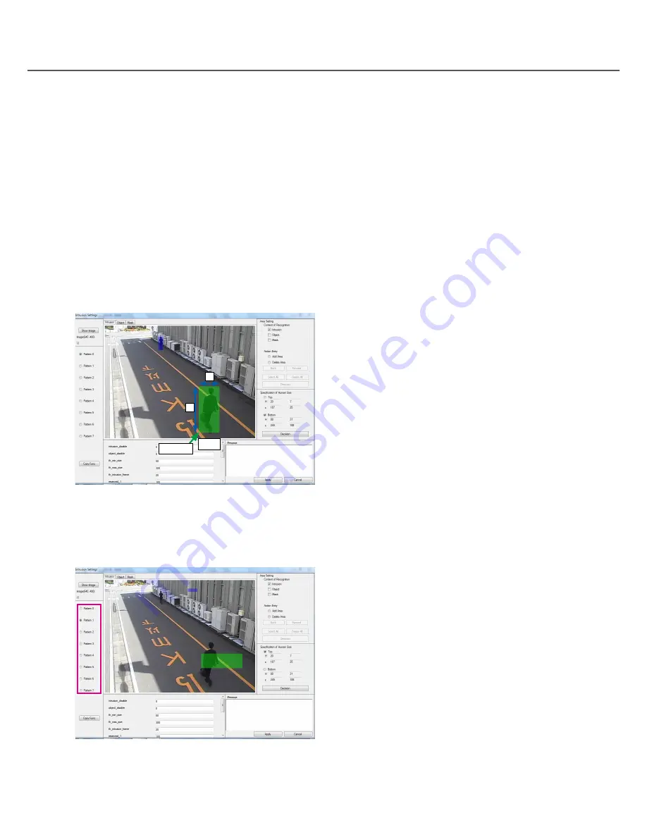
Validity of image top end and bottom end

The following conditions are required because the image top end and bottom end are the areas that show the 
size of the innermost human and the size of the most front human, respectively:

① 

The y coordinate of the image top end shall be upper in comparison with the y coordinate of the image bot-
tom end. (The same position for both ends unconfigurable).

② 

The H value of the image top end shall be smaller in comparison with the H value of the image bottom end.

③ 

The V value of the image top end shall be the same or smaller in comparison with the V value of the image 
bottom end.

What is "H", "V", "x" and "y" values

"H", "V", "x" and "y" shows the setting size and position of the rectangular that is specified at specifying the 
image top end/bottom end and saved in the converted size when Image display area was 640 × 480.
 

H:  Value of the selected rectangular width


V:  Value of the selected rectangular height


x:  x-coordinate of the center bottom of the rectangular


y:  y-coordinate of the center bottom of the rectangular

Pattern switching

Selection among Patterns 0 to 7 allows the parameter to be edited to be changed. After switching Patterns, the 
same setting operation is performed on each Pattern.

V

Bottom

×

H

(x, y)

Summary of Contents for AF-FX100

Page 1: ...is product please read these instructions carefully and save this manual for future use The model number is abbreviated in some descriptions in this manual Setup Instructions Intrusion Detection Image Recognition BOX Model No AF FX100 AF FX110 ...

Page 2: ...parameter for the image recognition library 22 Download the parameter for the image recognition library 23 BOX reboot 24 Update of the image recognition library 25 Initialization of BOX setting information 26 Check the resource of the BOX 27 Check the image processing status of the BOX 27 Check syslog of the BOX 28 Obtain the syslog data file of the BOX 29 Obtaining version information of the BOX ...

Page 3: ... OF THE PRODUCT 3 ANY LOSS OR DAMAGE CAUSED BY INAPPROPRIATE USE NEGLIGENT OPERATION OR MISTAKEN SETUP OF THE USER INCLUDING WITHOUT LIMITATION ANY DAMAGE CAUSED BY DIVULGING OF UNINTENDED INFORMATION LOSING PASSWORD OR USED PASSWORD BY THE THIRD PERSONS 4 ANY DAMAGE CAUSED BY DISASSEMBLE REPAIR OR MODIFICATION OF THE PRODUCT BY A PERSON OR ENTITY OTHER THAN Panasonic System Networks Co Ltd OR THE...

Page 4: ...z or faster Memory 2 GB or more Monitor 1 024 x 768 pixels or more 24 bit True color or better Network interface A 100 1000 Mbps network interface card must be installed Web browser Windows Internet Explorer 8 0 Other CD ROM drive It is necessary to refer to the operating instructions on the provided CD ROM Adobe Reader It is necessary to refer to the operating instructions on the provided CD ROM ...

Page 5: ...rmit from the authorities con cerned on your own responsibility Abbreviations The following abbreviations are used in this manual Microsoft Windows 7 Professional 32 bit Edition is referred to as Windows 7 hereafter Image Recognition BOX is referred to as BOX hereafter Network security As you will use this unit connected to a network your attention is called to the following security risks Leakage...

Page 6: ...ent such as inappropriate installation location or information leakage or outflow caused by inadequacies in definition and setting of access authority Authentication information Our system support center will never ask customer s password by e mail or telephone Caution in disposing of or transferring this unit When this unit is disposed of or transferred be sure to erase the data to prevent inform...

Page 7: ...emoval detection allows an alarm to be issued when object abandonment removal occurs in the areas To issue an alarm the status of object abandonment removal needs to last for 10 sec or more Up to 8 object abandonment removal can be simultaneously detected by 1 camera A 9th or higher object can not be detected The detected status is cancelled approx 60 sec after detection when alarm automatic can c...

Page 8: ...ult IP address 192 168 10 10 User name admin Password panasonic MAINTENANCE lamp top red bottom green Not used MAINTENANCE Maintenance port Not used LAN1 Network port 1 Not used LAN2 Network port 2 Connects to the system network Default IP address 192 168 10 10 SIGNAL GND SIGNAL GND terminal Connect this terminal to a SIGNAL GND terminal of a device other than this unit in the system or the frame ...

Page 9: ...rval 80 ms 2 DG NW960 Camera title Date time display setting OFF JPEG setting VGA 10 fps MPEG 4 setting OFF Audio setting Interactive Full duplex 32 kbps Mic input volume Middle Mic input interval 80 ms 3 DG NS202A Camera title Date time display setting OFF JPEG setting VGA 10 fps MPEG 4 setting OFF Audio setting Interactive Full duplex 32 kbps Mic input volume Middle Mic input interval 80 ms 4 DG...

Page 10: ...D400 DG ASM100 or DG ND400 5 Communication with control section Interactive This is a telegraphic message between the PC software package AF SX100S and BOX This is equipped with a function where a detection factor is received from the BOX and information such as detection cancellation test alarm and detection inhibition is sent to the BOX AF SX100S Be aware of the following when the BOX is registe...

Page 11: ...11 HUB Select auto negotiation for the hub port to which the BOX is connected Failure to observe this may cause abnormal operation when images are received for example ...

Page 12: ...ich the BOX parameters are specified on the connected PC Page 14 Change the BOX setting with use of a Web browser via the connected PC Page 16 Specify the BOX parameters with use of the parameter setting application via the connected PC Page 31 Setting of connected PC Change the network setting and the web browser setting of the PC to conform to the settings of the BOX Page 13 The procedure below ...

Page 13: ...dress of the PC capable of accessing the BOX without any duplication of the IP address assigned to the BOX and the IP address of any one of devices connected to the network Web browser setting of PC All the access to the BOX is performed via the Web Follow the steps below to obtain correct display 1 Click Tools and Internet Options and select Advanced tab 2 Uncheck Show friendly HTTP error message...

Page 14: ...r Application Setup Wizard window will be displayed Caution When using this application it is necessary that NET Framework 3 5 is installed on the PC If NET Framework 3 5 has not been installed on the PC on which the parameter setting application is installed in advance of installing the parameter setting application install NET Framework 3 5 Step 3 Click the Next button Wait until the confirmatio...

Page 15: ...eter setting application common ini Setting file for parameter setting application tar32 dll tar32 library c panasonic box ja SettingParameter resources dll Japanese resource c panasonic box default appli ini Default configuration parameter of the library independent parameter avmd ini Default configuration parameter for the intru sion detection setting parameter cde_wwd ini Unused face ini Unused...

Page 16: ...yed Step 2 Enter the user name and password Default User name admin Password panasonic If the username or password is changed at Web set ting enter the updated username or password The main window will be displayed Note A plurality of users are not supported Renaming the username and password is recom mended from the viewpoint of security Refer to Change the user name and password for the BOX page...

Page 17: ...0 The settings are performed 1 IP address setting IP Address setting page 18 2 BOX authentication setting User name or pass word change for the BOX page 20 3 Camera authentication setting User name or password change for the camera page 21 4 Parameter update Parameter update for the image recognition library page 22 5 Parameter download Parameter download for the image recognition library page 23 ...

Page 18: ...tep 2 Select 1 IP address setting The address setting window will be displayed Step 3 After entering each IP address page 19 click the Execute button The reboot request window will be displayed Step 4 Click the reboot button The success window will be displayed The BOX restarts If one of the steps fails the failure screen is dis played In such a case go back to Step 1 and try again ...

Page 19: ...box tar gz is filled with 12 digits IP address with dots deleted and octets zero filled Ex When the IP address of the BOX is 192 168 10 10 the folder name is 192168010010 5 IP address of the syslog server SYSLOG Server If the syslog of the BOX is saved on an external syslog server this address is specified Otherwise leave this blank Note If any one of the IP addresses is a duplication of one of ot...

Page 20: ...tration details The success window will be displayed when the registration is successful This unregistered window will be displayed when the registration is unsuccessful Note If you forget the username and password for the BOX the initial username and password resume by setting the rotary switch on the rear panel to 8 and turning the power off and then on After making sure that the initial usernam...

Page 21: ...uration page page 17 The setup window will be displayed Step 2 Select 3 Camera authentication setting The change window for the camera login user name and password will be displayed Step 3 Click the Execute button after entering the user name and password The reboot window will be displayed when the registration is successful The success window will be displayed when the reboot is successful Cauti...

Page 22: ...ed Step 2 Select 4 Parameter update The parameter update window will be displayed Step 3 Click the Browse button and select the parameter file box tar gz to be updated Click the Upload but ton after selecting the file The update success and reboot window will be displayed Step 4 Click the reboot button The success window will be displayed when the reboot is successful When a file with a format oth...

Page 23: ...for image recognition go to parameter setting application Step 1 Select 2 Settings on the BOX configuration page page 17 The setup window will be displayed Step 2 Select 5 Parameter download The parameter download window will be displa yed Step 3 Click Click here to execute The File Download dialog will be displayed Click the Save button and download the parameter in the selected folder ...

Page 24: ...X control on the BOX configuration page page 17 The BOX control window will be displayed Step 2 Select 1 Reboot The reboot window will be displayed Step 3 Click Click here to execute The BOX will be rebooted and the success win dow will be displayed ...

Page 25: ...played Step 2 Select 2 Firmware update The recognition library update window will be displayed Step 3 Click the Browse button Select the recognition library file to be updated and click the Update but ton While data is being transferred or written the recogni tion library updating window is displayed Step 4 When the update is complete the update success and reboot window will be displayed Step 5 C...

Page 26: ...e factory initial setting The setting information to be initialized consists of the following 1 Parameter for the image recognition library 2 BOX IP address information 3 Authentication information for the camera user Step 1 Select 3 BOX control on the BOX configuration page page 17 The BOX control window will be displayed Step 2 Select 3 Reset BOX to default The confirming initialization window w...

Page 27: ...splayed Step 2 Select 1 Resources The resource window will be displayed Check the image processing status of the BOX The image processing status of the BOX is viewable When contacting us please let us know the contents on the image processing status window Step 1 Select 1 Status check on the BOX configuration page page 17 The setup confirmation window will be displayed Step 2 Select 2 Processing s...

Page 28: ... configuration page page 17 The setup confirmation window will be displayed Step 2 Select 3 Logs The log window will be displayed The reslog and syslog fields are displayed on the window Refer to the syslog field for system log check Note The available capacity for saving system logs in the BOX is up to 32 MB When saved system logs fully occupy the available capacity no more sys tem log can be sav...

Page 29: ...end us the downloaded file Step 1 Select 1 Status check on the BOX configuration page page 17 The setup confirmation window will be displayed Step 2 Select 4 Log download The syslog download window will be displayed Step 3 Click Click here to execute The File download window will be displayed Save the file appropriately ...

Page 30: ...tacting us please let us know the contents on the version number window Step 1 Select 1 Status check on the BOX configuration page page 17 The setup confirmation window will be displayed Step 2 Select 5 Version The version number window will be displayed The version of the above image may differ from the actual version ...

Page 31: ... save folder is C panasonic box The save folder for the setting file of the BOX that is set to 192 168 10 10 is shown below C panasonic box 192168010010 box tar gz If the save folder is not specified the parameter setting application is terminated Therefore be sure to specify the save folder The save folder cannot be changed after start up of the parameter setting application If the save folder ne...

Page 32: ...cate with the BOX Step 1 Select Login from the menu bar BOX Utility The BOX login information setting dialog will be displayed Step 2 Click the OK button after entering the user name and the password The entered username and pass word are saved in the application and used at com munication with the BOX Clicking the Cancel button allows the entered user name and password to be discarded In the case...

Page 33: ...l be displayed Clicking the Cancel button allows the entered user name and password to be discarded Step3 When the camera authentication information setting is successful rebooting the BOX and version acquisi tion are automatically done When the version acqui sition is successful a pop up window of version information is displayed The version of the above image may differ from the actual version I...

Page 34: ...n be edited The folder that parameters are read into is made in the save folder The folder is named with 12 digits IP address with dots deleted and octets zero filled Ex When the IP address of the BOX is 192 168 10 10 the folder name is 192168010010 Step 2 Downloading from the BOX will start Communication can be canceled Refer to Canceling communication with the BOX page 58 for further information...

Page 35: ...compressed a work folder application installation folder temp is created and the work folder is deleted after parameter reading Therefore do not create a folder whose name is the same as the name of the work folder otherwise the folder with the same name of the work folder will be deleted Editing parameter If menu bar Parameter Setting is pointed after parameter reading editable parameters become ...

Page 36: ...ayed a Description of setting b Range c Default Apply button Cancel button General setting edit window General edit is performed Display the main window for the parameter setting Select General from the menu bar Parameter Setting The edit window for General is displayed a b c ...

Page 37: ...e 2 setting value 3 setting value N Any of setting values 1 to N Parameter check After parameter editing selection of another parame ter allows the parameter check function to be acti vated The function checks that the parameter was appropriately edited and if the editing is inappropri ate the entry area of the edited parameter becomes red and an error pop up is displayed Parameter editing again a...

Page 38: ...e displayed Show Image Pattern switching Parameter copy Tab switching Image display area Area information display area Human size display area Parameter name Editing parameter Area information setting Human size setting Message box Apply button Cancel button If the settings are not applied click the No button This operation applies the setting only but cannot save the setting Refer to Save and upd...

Page 39: ... displayed When the image capturing is successful the image from the camera will be displayed in the image dis play area The image will be resized and displayed while main taining the aspect ratio of the image display area Communication can be canceled Refer to Canceling communication with the BOX page 58 for further information about canceling communication The edit flow is explained below 1 Imag...

Page 40: ...ep 1 Click the Get Image from FILE button The image selection dialog will be displayed Select the JPEG image The opened JPEG file will be displayed in the image display area The image will be resized and displayed while main taining the aspect ratio of the image display area ...

Page 41: ...itching in accor dance with time zones up to 8 Patterns of param eters are available Step 3 Select a copy source Pattern Pattern 0 Pattern 1 Pattern 2 Pattern 3 Pattern 4 Pattern 5 Pattern 6 Pattern 7 Default Pattern 0 Step 4 Select a copy destination Pattern When ALL is selected the parameter is copied to the all Pattern ALL Pattern 1 Pattern 2 Pattern 3 Pattern 4 Pattern 5 Pattern 6 Pattern 7 De...

Page 42: ... of Area Setting at the same time Object tab The area information on Object is displayed in the area information display area Object is checked in Content of Recognition of Area Setting at the same time Mask tab The area information on Mask is displayed in the area information display area Mask is checked in Content of Recognition of Area Setting at the same time If the tab is switched when Specif...

Page 43: ...s with lines and addition of 3 or more area points makes an enclosed area Every time right click is performed a newly added area point is deleted Step 4 Click the Decision button to confirm the selected area points The window that reflects the additional area will be displayed To enclose an area at least 3 area points are needed An area enclosed with more than 30 points cannot be added and an erro...

Page 44: ...ation page 43 Designation of a plurality of area points links among area points with lines and addition of 3 or more area points makes an enclosed area Every time right click is performed a newly added area point is deleted Step 4 Click the Decision button to confirm the selected area points The window that reflects the deleted area will be displayed To enclose an area at least 3 area points are n...

Page 45: ...fy all areas Step 1 Select the content of recognition Select Content of Recognition of the area setting to specify all areas If both Intrusion and Object are checked area information on both in all areas is specified Step 2 Click the Select All button The warning pop up window will be displayed Step 3 Select Yes to specify the all area The specified all area window will be displayed STEP1 STEP2 ...

Page 46: ...p 1 Select the content of recognition Select Content of Recognition of the Area Setting to delete all areas If both Intrusion and Object abandonment removal are checked area information on both in all areas is deleted Step 2 Click the Delete All button The warning pop up window will be displayed Step 3 Select Yes to delete the all area The window will be displayed without all areas STEP1 STEP2 ...

Page 47: ... area information are recorded and press ing the Back and Forward buttons can go back and forth among the 10 pieces of the area information However if a tab or Pattern is switched the past area information is reset and the Back button is disabled Example of transition BWD FWD FWD BWD FWD FWD BWD BWD Latest 10 times before the present 1 time before the present 2 times before the present Omitted ...

Page 48: ...ecify Top of Specification of Human Size Step 1 Select the Top position of Specification of Human Size Step 2 After left clicking a point on the human size display area select a rectangular area by dragging After selecting a rectangular area right click the area to display the previous settings Resetting can also be performed by left clicking and dragging again Step 3 Click the Decision button to ...

Page 49: ...a by dragging After selecting a rectangular area right click the area to display the previous settings Resetting can also be performed by left clicking and dragging again Step 3 Click the Decision button to check the selected rect angular area The setting values take effect H V x and y in the Specification of Human Size field Lower selected rectangular area of the screen Lower selected area of the...

Page 50: ...he image top end shall be the same or smaller in comparison with the V value of the image bottom end What is H V x and y values H V x and y shows the setting size and position of the rectangular that is specified at specifying the image top end bottom end and saved in the converted size when Image display area was 640 480 H Value of the selected rectangular width V Value of the selected rectangula...

Page 51: ...he setting is appropriate the parameter can be set However if the setting is not appropriate an error pop up is displayed and the parameter cannot be set If the settings are not applied click the No button This operation takes effect the setting only but cannot save the setting Refer to Save and update the parameter page 52 for how to save settings ...

Page 52: ...amed with 12 digits IP address with dots deleted and octets zero filled For the IP address of 192 168 10 10 the folder name becomes 192168010010 Caution When a parameter is saved in the IP address folder a work folder C panasonic box temp is created and the work folder is deleted after the parameter is compressed and saved in the IP address folder Therefore do not create a folder whose name is the...

Page 53: ...older whose name is the same as the name of the work folder other wise the folder with the same name of the work folder will be deleted Step 3 When parameter updating to the BOX is successful rebooting the BOX and version acquisition are auto matically done When the version acquisition is suc cessful a pop up window of version information is displayed The version of the above image may differ from...

Page 54: ...rts Version acquisition can be canceled Refer to Canceling communication with the BOX page 58 for further information about canceling communication Step 3 When the version acquisition is successful the pop up window of the version information will be dis played The version of the above image may differ from the actual version Step 4 Click the OK button The main window will be displayed again ...

Page 55: ...plication version Step 1 Select About from the menu bar Help Step 2 The pop up window of the version information will be displayed Click the OK button The version of the above image may differ from the actual version How to update the program The program of the BOX is updated ...

Page 56: ...on Step 3 When program updating to the BOX is successful rebooting the BOX and version acquisition are auto matically done When the version acquisition is suc cessful a pop up window of version information is displayed The version of the above image may differ from the actual version In this case a portion of version information isn t often acquired and displayed because of the timing of version a...

Page 57: ...ooting the BOX and version acquisition are automatically done When the version acquisition is successful a pop up window of version information is displayed The version of the above image may differ from the actual version In this case a portion of version information isn t often acquired and displayed because of the timing of version acquisition But restarting is successful if the pop up window o...

Page 58: ...ked by version acquisition or parameter download from the BOX Even when communication with the BOX cannot be performed retry repeats until communication is estab lished If communication errors occur repeatedly cancel the communication After a cancellation by clicking Cancel the status before communication being established resumes How to exit from application Select Exit from the menu bar Paramete...

Page 59: ... from the application without saving edited parameters an alarming pop up message is displayed If exiting from the application without saving click the Yes button If the parameters should be saved click the No button ...

Page 60: ...es Step 4 Click Uninstall on the menu bar The Programs and Features window will be displayed If the message of Do you want to allow the following program from an unknown publisher to make changes to this computer may be displayed due to user account control click the Yes button Wait until completion of uninstallation Check the uninstallation Check that all the installed files page 15 are deleted H...

Page 61: ...nt log5 txt log5 txt log file at 5 times before the present log6 txt log6 txt log file at 6 times before the present log7 txt log7 txt log file at 7 times before the present log8 txt log8 txt log file at 8 times before the present log9 txt log9 txt log file at 9 times before the present Deletion Caution The available capacity for log files is up to 1 MB When saved log files fully occupy the availa...

Page 62: ...G NT314 and register BOX_2 In the device tree panel 4 camera icons are displayed Whichever camera icon is selected the same image via Camera 2 is displayed When camera control is performed on DG ASM100 The input port number camera icon of the BOX encoder icon connected to the applicable camera needs to be selected b Connect the analog camera 3 to Input 3 of DG NT314 and register BOX_3 To control t...

Page 63: ...urs a Even Camera 3 is registered with CH3 of the encoder and an event occurs in the area of Camera 3 the display shows that an alarm occurs in the area of Camera 1 b Decide by the encoder name displayed in the device tree panel b a ...

Page 64: ...sses of IP cameras and encoders are registered E g 1 192 168 10 20 IP camera E g 2 192 168 10 21 Encoder 4 CamChannel channel of encoder ip camera s channel is always 1 Mandatory When an encoder is registered with CamIpAddr image input number is entered E g 1 1 only 1 at IP camera E g 2 3 Encoder LOCK DG S C385 OPEN CamIpAddr 192 168 10 20 CamChannel 1 CamIpAddr 192 168 10 21 CamChannel 3 KanshiSe...

Page 65: ...cified E g 192 168 10 30 8 OriginalAlarmIpAddr original alarm notification PC ip_address MAX 8 Optional Up to 8 IP addresses of DG ND400 or PCs on which DG ASM100 is installed can be registered 1 Unless otherwise specified leave this blank When an alarm is detected noti fication is performed E g 1 192 168 10 31 E g 2 192 168 10 32 9 OriginalAlarmPort original alarm notification PC port Fixed This ...

Page 66: ...n of image with pro cessing results 1 OSD image DG ASM100 DG ND400 encoder or the like Up to 8 IP addresses can be registered Unless otherwise specified leave this blank E g 192 168 10 32 15 AlarmAutoDeactivate use alarm auto deacti vate 0 Auto 1 Manual Mandatory This holds the alarm status in the BOX and decides whether or not to newly perform detection 0 for automatic cancellation 1 for retainme...

Page 67: ...Mid 1 Low 6 Increase in the sensitivity enhances the detection capability when human is not detected in the night time but is likely to cause excessive detection 0 more detectable 6 less detectable 10 th_object_frame alarm threshold of object frame Time from object abandonment removal to alarm issued is specified Setting value 1 600 Setting value x 100 frames Represented for 10 fps 10 6000 sec 11 ...

Page 68: ...68 Standard Accessories Installation Guide 1 pc AC adapter 1 pc CD ROM 1 pc The CD ROM contains the Setup Instructions PDF parameter setting application etc ...

Page 69: ... MediaProServices PSC us panasonic com Panasonic System Networks Co Ltd 2011 N0911 0 PYQP1002ZA J1 Printed in Japan For Europe and other countries Panasonic Corporation http panasonic net Importer s name and address to follow EU rules Panasonic Testing Centre Panasonic Marketing Europe GmbH Winsbergring 15 22525 Hamburg F R Germany ...

Reviews: