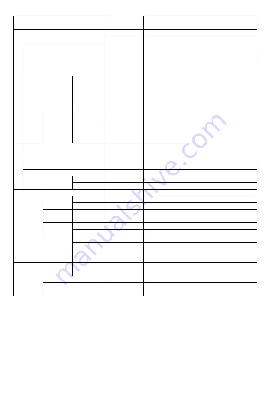
background image

26 

Indoor 

Model 

CS-RZ80TKR 

POS (EAN) 

5025232871391 

Outdoor 

Model 

CU-RZ80TKR 

POS (EAN) 

5025232871582 

Indoor Fan


Type 

Cross-flow Fan 

Material 

ASG33 

Motor Type 

DC (8-poles) 

Input Power 

105.0 

Output Power 

40 

Speed 

QLo 

Cool 

rpm 

870 

Heat 

rpm 

950 

Lo 

Cool 

rpm 

970 

Heat 

rpm 

1050 

Me 

Cool 

rpm 

1160 

Heat 

rpm 

1220 

Hi 

Cool 

rpm 

1350 

Heat 

rpm 

1400 

SHi 

Cool 

rpm 

1450 

Heat 

rpm 

1450 

Outdoo

r Fa

n


Type 

Propeller Fan 

Material 

PP 

Motor Type 

DC (8-poles) 

Input Power 

Output Power 

60 

Speed 

Hi 

Cool 

rpm 

720 

Heat 

rpm 

720 

Moisture Removal 

L/h (Pt/h) 

4.7 (9.9) 

Indoor Airflow 

QLo 

Cool 

m³/min (ft³/min) (L/s) 

13.91 (491) (232) 

Heat 

m³/min (ft³/min) (L/s) 

15.41 (544) (257) 

Lo 

Cool 

m³/min (ft³/min) (L/s) 

15.83 (559) (264) 

Heat 

m³/min (ft³/min) (L/s) 

17.32 (612) (287) 

Me 

Cool 

m³/min (ft³/min) (L/s) 

19.46 (687) (324) 

Heat 

m³/min (ft³/min) (L/s) 

20.56 (726) (343) 

Hi 

Cool 

m³/min (ft³/min) (L/s) 

23.10 (815) (385) 

Heat 

m³/min (ft³/min) (L/s) 

24.0 (845) (400) 

SHi 

Cool 

m³/min (ft³/min) (L/s) 

25.01 (883) (416) 

Heat 

m³/min (ft³/min) (L/s) 

24.95 (881) (415) 

Outdoor Airflow 

Hi 

Cool 

m³/min (ft³/min) 

55.8 (1970) 

Heat 

m³/min (ft³/min) 

55.8 (1970) 

Refrigerant 

Cycle 

Control Device 

Expansion Valve 

Refrigerant Oil 

cm³ 

FW50S (800) 

Refrigerant Type 

g (oz) 

R32, 1.49k (52.6) 


Summary of Contents for 5025232871346

Page 1: ...This Air Conditioner contains and operates with refrigerant R32 THIS PRODUCT MUST ONLY BE INSTALLED OR SERVICED BY QUALIFIED PERSONNEL Refer to Commonwealth State Territory and local legislation regulations codes installation operation manuals before the installation maintenance and or service of this product E CONO MY i AUTO X ANTI BACTERIAL FILT ER T IMER P OWER ECO NOMY ANTI BACTERIAL FILTER PO...

Page 2: ...nd Service 81 13 7 Repairing of refrigerant cycle Brazing point 85 13 8 Reference Analysis method for no error code no cooling no warming 91 14 Operation and Control 93 14 1 Basic Function 93 14 2 Indoor Fan Motor Operation 95 14 3 Outdoor Fan Motor Operation 96 14 4 Airflow Direction 96 14 5 Quiet Operation Cooling Mode Cooling Area of Dry Mode 98 14 6 Quiet Operation Heating 99 14 7 Powerful Mod...

Page 3: ...rs or other objects into the unit high speed rotating fan may cause injury 7 Do not sit or step on the unit you may fall down accidentally 8 The appliance shall be installed and or operated in a room with floor area larger than A min m 2 refer Table A and keep away from ignition sources such as heat sparks open flame or hazardous areas such as gas appliances gas cooking reticulated gas supply syst...

Page 4: ... contacts with fire 28 Be aware that refrigerants may not contain an odour 29 This equipment must be properly earthed Earth line must not be connected to gas pipe water pipe earth of lightning rod and telephone Otherwise it may cause electrical shock in case of equipment breakdown or insulation breakdown 30 Do not modify the machine part material during repairing service 31 If wiring unit is suppl...

Page 5: ...t to 700 20 F 370 10 C Pb free solder will tend to splash when heated too high about 1100 F 600 C 11 Do not touch the sharp aluminum fins or edges of metal parts If you are required to handle sharp parts during installation or servicing please wear hand glove Sharp parts may cause injury 12 Tighten the flare nut with torque wrench according to specified method If the flare nut is over tightened af...

Page 6: ...dited assessment authority which authorizes their competence to handle refrigerants safely in accordance with an industry recognised assessment specification Servicing shall only be performed as recommended by the equipment manufacturer Maintenance and repair requiring the assistance of other skilled personnel shall be carried out under the supervision of the person competent in the use of flammab...

Page 7: ...ing the system That there is continuity of earth bonding At all times the manufacturer s maintenance and service guidelines shall be followed If in doubt consult the manufacturer s technical department for assistance If a fault exists that could compromise safety then no electrical supply shall be connected to the circuit until it is satisfactorily dealt with If the fault cannot be corrected immed...

Page 8: ...Hoses or lines shall be as short as possible to minimize the amount of refrigerant contained in them Cylinders shall be kept upright Ensure that the refrigeration system is earthed prior to charging the system with refrigerant Label the system when charging is complete if not already Extreme care shall be taken not to over fill the refrigeration system Prior to recharging the system it shall be pr...

Page 9: ...equipment that is at hand and shall be suitable for the recovery of concerning the equipment that is at hand and shall be suitable for the recovery of flammable refrigerants In addition a set of calibrated weighing scales shall be available and in good working order Hoses shall be complete with leak free disconnect couplings and in good condition Before using the recovery machine check that it is ...

Page 10: ...r Noise H L QLo dB A 40 25 19 40 25 19 Power Level dB 56 41 35 56 41 35 Outdoor Noise H L QLo dB A 48 48 Power Level dB 63 63 Heating Capacity kW 0 80 3 00 3 60 0 80 3 00 3 00 BTU h 2730 10200 12300 2730 10200 12300 Kcal h 690 2580 3100 690 2580 3100 Running Current A 3 50 3 40 Input Power W 195 730 1 04k 195 730 1 04k COP COP CLASS W W 4 10 4 11 3 5 3 46 4 10 4 11 3 5 3 46 COP BTU hW 14 00 13 97 ...

Page 11: ...Power W 40 Speed Hi Cool rpm 840 Heat rpm 840 Moisture Removal L h Pt h 1 5 3 2 Indoor Airflow QLo Cool m min ft min L s 5 27 186 88 Heat m min ft min L s 6 05 213 101 Lo Cool m min ft min L s 6 51 230 108 Heat m min ft min L s 7 40 261 123 Me Cool m min ft min L s 9 01 318 150 Heat m min ft min L s 9 80 346 163 Hi Cool m min ft min L s 11 5 405 192 Heat m min ft min L s 12 2 430 203 SHi Cool m mi...

Page 12: ...5 x 17 Size W x H x L mm 610 x 315 x 25 4 Outdoor Heat Exchanger Fin Material Aluminium Blue Coat Fin Type Corrugated Fin Row x Stage x FPI 2 x 24 x 17 Size W x H x L mm 18 2 x 504 x 710 Air Filter Material Polypropelene Type One touch Power Supply Outdoor Power Supply Power Supply Cord NIL Thermostat Electronic Control Protection Device Electronic Control Dry Bulb Wet Bulb Indoor Operation Range ...

Page 13: ...se H L QLo dB A 42 26 19 42 26 19 Power Level dB 58 42 35 58 42 35 Outdoor Noise H L QLo dB A 48 48 Power Level dB 63 63 Heating Capacity kW 0 80 3 70 5 10 0 80 3 70 5 10 BTU h 2730 12600 17400 2730 12600 17400 Kcal h 690 3180 4390 690 3180 4390 Running Current A 4 35 4 20 Input Power W 200 950 1 42k 200 950 1 42k COP COP CLASS W W 4 00 3 89 3 0 3 59 4 00 3 89 3 0 3 59 COP BTU hW 13 65 13 26 12 25...

Page 14: ...Power W 40 Speed Hi Cool rpm 830 Heat rpm 880 Moisture Removal L h Pt h 2 0 4 2 Indoor Airflow QLo Cool m min ft min L s 4 94 174 82 Heat m min ft min L s 6 76 239 113 Lo Cool m min ft min L s 6 46 228 108 Heat m min ft min L s 8 57 303 143 Me Cool m min ft min L s 8 93 315 149 Heat m min ft min L s 10 29 363 171 Hi Cool m min ft min L s 11 4 400 190 Heat m min ft min L s 12 1 425 202 SHi Cool m m...

Page 15: ...x 21 Size W x H x L mm 610 x 315 x 25 4 Outdoor Heat Exchanger Fin Material Aluminium Blue Coat Fin Type Corrugated Fin Row x Stage x FPI 2 x 24 x 17 Size W x H x L mm 36 4 x 504 x 713 684 Air Filter Material Polypropelene Type One touch Power Supply Outdoor Power Supply Power Supply Cord NIL Thermostat Electronic Control Protection Device Electronic Control Dry Bulb Wet Bulb Indoor Operation Rang...

Page 16: ...dB A 44 34 31 44 34 31 Power Level dB 60 50 47 60 50 47 Outdoor Noise H L QLo dB A 48 43 48 43 Power Level dB 63 58 63 58 Heating Capacity kW 0 98 5 80 7 80 0 98 5 80 7 80 BTU h 3340 19800 26600 3340 19800 26600 Kcal h 840 4990 6710 840 4990 6710 Running Current A 6 90 6 80 Input Power W 340 1 54k 2 30k 340 1 54k 2 30k COP COP CLASS W W 2 88 3 77 2 5 3 39 2 88 3 77 2 5 3 39 COP BTU hW 9 82 12 86 1...

Page 17: ...W 40 Speed Hi Cool rpm 820 Heat rpm 800 Moisture Removal L h Pt h 2 8 5 9 Indoor Airflow QLo Cool m min ft min L s 12 99 459 216 Heat m min ft min L s 11 41 403 190 Lo Cool m min ft min L s 14 96 528 249 Heat m min ft min L s 13 39 473 223 Me Cool m min ft min L s 17 33 612 289 Heat m min ft min L s 16 74 591 279 Hi Cool m min ft min L s 19 9 700 332 Heat m min ft min L s 20 3 715 339 SHi Cool m m...

Page 18: ...x 17 Size W x H x L mm 836 5 x 357 x 25 4 Outdoor Heat Exchanger Fin Material Aluminium Blue Coat Fin Type Corrugated Fin Row x Stage x FPI 2 x 28 x 17 Size W x H x L mm 36 4 x 588 x 781 3 752 7 Air Filter Material Polypropelene Type One Touch Power Supply Outdoor Power Supply Power Supply Cord NIL Thermostat Electronic Control Protection Device Electronic Control Dry Bulb Wet Bulb Indoor Operatio...

Page 19: ...B A 46 36 33 46 36 33 Power Level dB 62 52 49 62 52 49 Outdoor Noise H L QLo dB A 49 44 49 44 Power Level dB 64 59 64 59 Heating Capacity kW 0 98 6 50 8 00 0 98 6 50 8 00 BTU h 3340 22200 27300 3340 22200 27300 Kcal h 840 5590 6880 840 5590 6880 Running Current A 8 40 8 20 Input Power W 285 1 89k 2 64k 285 1 89k 2 64k COP COP CLASS W W 3 44 3 44 2 0 3 03 3 44 3 44 2 0 3 03 COP BTU hW 11 72 11 75 1...

Page 20: ...W 40 Speed Hi Cool rpm 880 Heat rpm 830 Moisture Removal L h Pt h 3 3 7 0 Indoor Airflow QLo Cool m min ft min L s 13 14 464 219 Heat m min ft min L s 13 91 491 232 Lo Cool m min ft min L s 15 06 532 251 Heat m min ft min L s 15 82 559 264 Me Cool m min ft min L s 17 73 626 295 Heat m min ft min L s 18 12 640 302 Hi Cool m min ft min L s 20 6 725 344 Heat m min ft min L s 20 6 725 344 SHi Cool m m...

Page 21: ...x 17 Size W x H x L mm 836 5 x 357 x 25 4 Outdoor Heat Exchanger Fin Material Aluminium Blue Coat Fin Type Corrugated Fin Row x Stage x FPI 2 x 28 x 17 Size W x H x L mm 36 4 x 588 x 856 3 827 7 Air Filter Material Polypropelene Type One Touch Power Supply Outdoor Power Supply Power Supply Cord NIL Thermostat Electronic Control Protection Device Electronic Control Dry Bulb Wet Bulb Indoor Operatio...

Page 22: ... A 49 37 34 49 37 34 Power Level dB 65 53 50 65 53 50 Outdoor Noise H L QLo dB A 52 47 52 47 Power Level dB 66 61 66 61 Heating Capacity kW 1 70 7 50 9 90 1 70 7 50 9 90 BTU h 5800 25600 33800 5800 25600 33800 Kcal h 1460 6450 8510 1460 6450 8510 Running Current A 9 10 8 80 Input Power W 380 2 06k 2 85k 380 2 06k 2 85k COP COP CLASS W W 4 47 3 64 2 5 3 47 4 47 3 64 2 5 3 47 COP BTU hW 15 26 12 43 ...

Page 23: ...W 40 Speed Hi Cool rpm 820 Heat rpm 880 Moisture Removal L h Pt h 4 1 8 7 Indoor Airflow QLo Cool m min ft min L s 13 51 477 225 Heat m min ft min L s 14 01 495 233 Lo Cool m min ft min L s 15 42 544 257 Heat m min ft min L s 16 02 566 267 Me Cool m min ft min L s 18 66 659 311 Heat m min ft min L s 19 46 687 324 Hi Cool m min ft min L s 22 10 780 369 Heat m min ft min L s 23 1 815 385 SHi Cool m ...

Page 24: ... 17 Size W x H x L mm 836 5 x 357 x 25 4 Outdoor Heat Exchanger Fin Material Aluminium Blue Coat Fin Type Corrugated Fin Row x Stage x FPI 2 x 31 x 19 Size W x H x L mm 36 4 x 651 x 904 5 874 5 Air Filter Material Polypropelene Type One Touch Power Supply Outdoor Power Supply Power Supply Cord NIL Thermostat Electronic Control Protection Device Electronic Control Dry Bulb Wet Bulb Indoor Operation...

Page 25: ...A 51 38 35 51 38 35 Power Level dB 67 54 51 67 54 51 Outdoor Noise H L QLo dB A 55 50 55 50 Power Level dB 69 64 69 64 Heating Capacity kW 2 20 9 00 11 00 2 20 9 00 11 00 BTU h 7500 30700 37500 7500 30700 37500 Kcal h 1890 7740 9460 1890 7740 9460 Running Current A 12 70 12 30 Input Power W 500 2 66k 3 30k 500 2 66k 3 30k COP COP CLASS W W 4 40 3 38 2 0 3 33 4 40 3 38 2 0 3 33 COP BTU hW 15 00 11 ...

Page 26: ... W 60 Speed Hi Cool rpm 720 Heat rpm 720 Moisture Removal L h Pt h 4 7 9 9 Indoor Airflow QLo Cool m min ft min L s 13 91 491 232 Heat m min ft min L s 15 41 544 257 Lo Cool m min ft min L s 15 83 559 264 Heat m min ft min L s 17 32 612 287 Me Cool m min ft min L s 19 46 687 324 Heat m min ft min L s 20 56 726 343 Hi Cool m min ft min L s 23 10 815 385 Heat m min ft min L s 24 0 845 400 SHi Cool m...

Page 27: ... 17 Size W x H x L mm 836 5 x 357 x 25 4 Outdoor Heat Exchanger Fin Material Aluminium Blue Coat Fin Type Corrugated Fin Row x Stage x FPI 2 x 30 x 19 Size W x H x L mm 38 1 x 762 x 895 8 865 8 Air Filter Material Polypropelene Type One Touch Power Supply Outdoor Power Supply Power Supply Cord NIL Thermostat Electronic Control Protection Device Electronic Control Dry Bulb Wet Bulb Indoor Operation...

Page 28: ...y Easy to use remote control Quality Improvement o Random auto restart after power failure for safety restart operation o Gas leakage protection o Prevent compressor reverse cycle o Inner protector to protect Compressor o Noise prevention during soft dry operation o Blue coated condenser for high resistance to corrosion Operation Improvement o Quiet mode to reduce the indoor unit operating sound o...

Page 29: ...louver Manually adjustable Indicator POWER TIMER i AUTO X ECONOMY Sunlight Sensor and Remote Control Receiver ECONOMY RZ50TKR RZ60TKR RZ71TKR RZ80TKR Air Filters Front panel Aluminium fin Anti bacterial filter Vertical airflow direction louver Do not adjust by hand Horizontal airflow direction louver Do not adjust by hand Auto OFF ON button Use when remote control is misplaced or a malfunction occ...

Page 30: ...FF ON Temperature setting Economy operation Economy operation Airflow direction adjustment Fan speed selection Temperature setting Clock setting Timer setting Timer setting Clock setting Fan speed selection Airflow direction adjustment iAUTO X operation Operation mode Quiet operation Powerful operation iAUTO X operation Operation mode Powerful Quiet operation RZ50TKR RZ60TKR RZ71TKR RZ80TKR RZ25TK...

Page 31: ...ole 799 197 92 8 55 60 60 41 61 410 290 60 41 22 Remote Control 144 5 59 Remote Control Holder 64 87 16 4 264 6 Unit mm B A C PIPE HOLE CENTER PIPE HOLE CENTER 128mm TO PIPE HOLE CENTER 128mm TO PIPE HOLE CENTER 496 6 128 184 222 128 Right piping hole Left piping hole Installation plate Indoor unit external dimensions line 420 380 45 95 Relative position between the indoor unit and the installatio...

Page 32: ... unit and the installation plate Front View 1102 244 135 60 135 60 41 61 Gas side Liquid side 410 302 42 6 61 Side View Side View Air intake direction Air outlet direction Left piping hole Right piping hole Remote Control Holder Remote Control 22 59 144 5 87 63 5 128 256 128 270 320 550 550 256 128 mm 748 Installation plate Indoor unit external dimensions line ...

Page 33: ...mm Side View Side View Front View Chassis Top View Unit mm 2 way valve at Liquid side High Pressure 3 way valve at Gas side Low Pressure 777 6 287 2 Ø 2 0 320 540 68 7 32 97 62 69 20 619 167 330 824 160 299 37 124 62 6 22 Side View Side View Front View Top View 2 way valve at Liquid side High Pressure 3 way valve at Gas side Low Pressure Space necessary for installation Anchor Bolt Pitch 320 x 570...

Page 34: ...131 72 875 35 82 360 5 131 Side View Side View Front View Top View Unit mm 2 way valve at Liquid side High Pressure 3 way valve at Gas side Low Pressure Anchor Bolt Pitch 360 5 613 Space necessary for installation 100 mm 100 mm 1000 mm Chassis 872 6 318 2 Ø 2 0 ...

Page 35: ...iew Unit mm Anchor Bolt Pitch 360 5 613 Space necessary for installation 100mm 100mm 1000mm 25 70 75 64 795 320 59 875 27 5 38 82 70 360 5 613 131 131 152 2 way valve at Liquid side High Pressure 3 way valve at Gas side Low Pressure Chassis 872 6 318 2 Ø 2 0 ...

Page 36: ...36 7 Refrigeration Cycle Diagram 7 1 CS RZ25TKR CU RZ25TKR CS RZ35TKR CU RZ35TKR ...

Page 37: ... 25 02 18 77 6 17 18 81 62 69 25 20 00 15 00 5 00 15 00 50 00 30 16 10 12 07 4 02 12 05 40 18 45 8 71 6 53 2 22 6 52 21 72 INDOOR OUTDOOR INTAKE TEMP SENSOR PIPE TEMP SENSOR 1 AIR TEMP SENSOR PIPE TEMP SENSOR LIQUID SIDE 2 WAY VALVE 3 WAY VALVE COMPRESSOR DISCHARGE MUFFLER COMPRESSOR TEMP SENSOR GAS SIDE COOLING HEATING HEAT EXCHANGER EVAPORATOR HEAT EXCHANGER CONDENSER EXPANSION VALVE 4 WAY VALVE...

Page 38: ...TOR Q1 Q35 Q36 D19 RY AC RY PWR DB103 D24 NTC NTC PTC PTC1 SC SC NTC REACTOR SINGLE PHASE POWER SUPPLY AC230 240V 50Hz TH2 TH3 4 WAY VALVE TH1 IC25 FUSE101 DB101 FUSE2 FUSE104 DRM FUSE103 U TEMP FUSE FUSE301 SEN1 FUSE3 NOISE FILTER L 1 2 3 1 2 3 C N MS 3 MS 3 M INDOOR UNIT OUTDOOR UNIT ...

Page 39: ...R UNIT 1 2 3 1 2 3 L N C INDOOR UNIT SINGLE PHASE POWER SUPPLY U FUSE 301 SC M TEMP FUSE M S 3 M S 3 IC25 DB101 FUSE2 FUSE3 Q35 Q36 D24 NTC TH2 FAN MOTOR COMPRESSOR Q1 FUSE101 _ RY PWR RY AC sc DB103 PTC PTC1 NTC TH3 D19 4 WAY VALVE _ REACTOR NTC TH1 FUSE104 FUSE103 SEN1 NOISE FILTER ...

Page 40: ...TER PFC CIRCUIT RECTIFCATION CIRCUIT RECTIFCATION CIRCUIT FUSE301 TEMP FUSE FUSE3 FUSE2 4 WAYS VALVE CT400 REACTOR NTC FUSE1 U V W P N TH2 DB3 DB2 CR3 RY HOT DRM U OUTDOOR UNIT INDOOR UNIT RY PWR2 RY AC PTC1 PTC2 NTC TH1 MS 3 SINGLE PHASE POWER SUPPLY AC230 240V 50 Hz ...

Page 41: ...5 UP DOWN LOUVER MOTOR INNER CN STM3 BLU 5 1 CN CNT WHT HAJEM A WHT 1 7 4 CN FM WHT REMARKS B BLU BLUE P PINK BR BROWN O ORANGE BL BLACK Y YLW YELLOW W WHT WHITE G GRN GREEN R RED GR GRAY Y G YELLOW GREEN 4 1 ELECTRONIC CONTROLLER DISPLAY RECEIVER CN DISP WHT CN DISP YLW 1 1 7 9 W W W W W W W COMMUNICATION CIRCUIT RECTIFICATION CIRCUIT GROUNDING TERMINAL Y G EVAPORATOR 1 W R G 2 3 BL AC303 WHT AC3...

Page 42: ...P PINK BR BROWN O ORANGE BL BLACK Y YLW YELLOW W WHT WHITE G GRN GREEN R RED GR GRAY Y G YELLOW GREEN FAN MOTOR M B BL Y W R t t 1 CN TH RED PIPING TEMP SENSOR 1 THERMISTOR 4 SUCTION TEMP SENSOR THERMISTOR SENSOR COMPLETE ELECTRONIC CONTROLLER DISPLAY RECEIVER CN DISP WHT CN DISP YLW 8 1 3 5 6 1 9 CN RCV YLW 1 4 W W W W W W W W COMMUNICATION CIRCUIT RECTIFICATION CIRCUIT GROUNDING TERMINAL Y G EVA...

Page 43: ... 2 3 TERMINAL BOARD L N YELLOW YEL OR T W TRADEMARK COMPRESSOR TERMINAL THE PARENTHESIZED LETTERS IS INDICATED ON TERMINAL COVER BLUE BLU OR S V RED RED OR R U CN TH1 WHT CN TANK WHT RED RED BLU BLU BLK PNK WHT YLW YLW U RED V BLU W YLW U V W 1 4 1 3 P N Q1 OUTDOOR AIR TEMP SENSOR THERMISTOR PIPING TEMP SENSOR THERMISTOR COMPRESSOR TEMP SENSOR THERMISTOR CN HOT WHT 1 3 ELECTRO MAGNETIC COIL 4 WAY ...

Page 44: ...ELLOW YEL OR T W TRADEMARK COMPRESSOR TERMINAL THE PARENTHESIZED LETTERS IS INDICATED ON TERMINAL COVER BLUE BLU OR S V RED RED OR R U CN TH1 WHT CN TANK WHT RED RED BLU BLU BLK PNK WHT YLW YLW U RED V BLU W YLW U V W 1 4 1 3 CN STM WHT 1 6 P N Q1 OUTDOOR AIR TEMP SENSOR THERMISTOR PIPING TEMP SENSOR THERMISTOR COMPRESSOR TEMP SENSOR THERMISTOR CN HOT WHT 1 3 ELECTRO MAGNETIC COIL 4 WAY VALVE ELEC...

Page 45: ... GRN BLK YLW DRM TO DRED ORG RED BRW WHT WHT ACN1 WHITE ACL1 BLACK COM3 RED L2 I GRAY L2 0 BLACK RECTIFICATION CIRCUIT RECTIFICATION CIRCUIT SWITCHING POWER SUPPLY CIRCUIT ELECTRONIC CONTROLLER MAIN PFC CIRCUIT Q10 1 1 1 3 3 1 1 6 4 4 7 P N U W V FUSE3 25A 250V CN COM YELLOW CN COM YELLOW CN BLK BLACK AC BLK BLACK AC WHT WHITE FUSE2 T3 15A L250V FUSE1 T2 5A L250V RED U BLUE V YELLOW W RED RED BLU ...

Page 46: ...0k SW01 1 2 R42 1k 12V 5V 5V F301 L6 L5 C57 C51 1000p R82 10k R90 10k C52 1000p 16 1 IC03 15 14 13 12 11 10 2 3 4 5 6 7 IC03 IC03 IC03 IC03 IC03 IC03 12V 5V C27 1u C25 1u R61 20 0k R62 15 0k 5V C3 0 1u R89 5V 12V E GND A C B Q201 R207 E GND A C B Q202 R208 LED204 R205 R206 LED203 R203 R204 5V 12V 12V LED202 R202 LED201 R201 REMOTE CONTROLLER FAN SPEED AIR SWING ECONOMY ON OFF SET CANCEL TIMER TEMP...

Page 47: ...M B BL Y W R t t 1 CN TH RED PIPING TEMP SENSOR 1 THERMISTOR 4 SUCTION TEMP SENSOR THERMISTOR SENSOR COMPLETE ELECTRONIC CONTROLLER DISPLAY RECEIVER CN DISP WHT CN DISP YLW 8 1 3 5 6 1 9 CN RCV YLW 1 4 W W W W W W W W COMMUNICATION CIRCUIT RECTIFICATION CIRCUIT GROUNDING TERMINAL Y G EVAPORATOR 1 W R G 2 3 BL AC303 WHT AC306 BLK AC304 RED G301 GRN FUSE301 T3 15A L250V NOISE FILTER CIRCUIT TEMP FUS...

Page 48: ...0 30 40 50 1 2 1 2 Outdoo r Air Sensor Outdoo r Heat Exchange r Sensor Compressor Temp Sensor Thermistor Characteristics 70 60 50 40 30 20 10 0 20 40 60 Temperature o C Re sistance k Ω 80 100 120 140 5V R14 10k G2 1 2 CN S The unit turn to the Rated Frequenc y Cooling Operation by short circuiting CN S after app lying power between the terminal 1 and 2 Operation of the compressor and the outdoor f...

Page 49: ...e r Sensor Compressor Temp Sensor Thermistor Characteristics 70 60 50 40 30 20 10 0 20 40 60 Temperature o C Re sistance k Ω 80 100 120 140 5V R14 10k G2 1 2 CN S The unit turn to the Rated Frequenc y Cooling Operation by short circuiting CN S after app lying power between the terminal 1 and 2 Operation of the compressor and the outdoor fan motor can be checked by applying power after short circui...

Page 50: ...T3 15 A L250V FUSE1 T2 5A L250V RED U BLUE V YELLOW W RED RED BLU BLK WHT BLU YLW YLW RED COMPRESSOR FAN MO TOR OUTDOORAIRTEMP SENSOR THERMIS TOR PIPINGTEMP SENSOR THERMIS TOR t t t CONNEC TOR WHITE MS 3 M 3 3 1 1 BLU YLW GRN YLW GRN YLW GRN COMMUNIC ATION CIRCUI T NOISE FI LTER CIRCUI T NOISE FI LTER CIRCUI T M CABINE T SIDE PLATE SOUND PROOF BOARD 5V R404 10k G2 1 2 CN S The unit turn to the Rat...

Page 51: ...rcuit Board 11 1 Indoor Unit 11 1 1 Main Printed Circuit Board 11 1 1 1 CS RZ25TKR CS RZ35TKR CN DISP JP1 Random Auto Restart Enable Disable AC304 AC303 HAJEM A CN FM G301 AC306 CN STM1 CN STM3 SW01 CN CNT CN RMT CN TH ...

Page 52: ...52 11 1 1 2 CS RZ50TKR CS RZ60TKR CS RZ71TKR CS RZ80TKR CN FM AC306 G301 AC304 JP1 Random Auto Restart Enable Disable CN DISP AC303 SW01 CN CNT CN STM1 CN STM2 CN STM3 CN RMT CN TH HAJEM A CN RCV ...

Page 53: ...ndicator and Receiver Printed Circuit Board 11 1 2 1 CS RZ25TKR CS RZ35TKR 11 1 2 2 CS RZ50TKR CS RZ60TKR CS RZ71TKR CS RZ80TKR CN DISP LED204 LED203 LED201 LED202 CN DISP LED206 LED205 LED203 LED201 LED204 LED202 ...

Page 54: ...inted Circuit Board 11 2 1 1 CU RZ25TKR CU RZ35TKR CU RZ50TKR CU RZ60TKR CU RZ71TKR POWER TRANSISTOR IPM CURRENT TRANSFORMER CT CN DEMAND CN TH1 CN MTR1 CN TANK CN HOT CN MTR2 CN V1 CN STM FOR RZ50 60 71TK ONLY AC BLK DATA AC WHT FG1 FG2 ...

Page 55: ...55 11 2 1 2 CU RZ80TKR CN HOT CN TANK CN TH1 CN EV CN FM AC BLK AC WHT CN DEMAND CN V1 CN COM CURRENT TRANSFORMER CT POWER TRANSISTOR IPM ...

Page 56: ... 11 2 2 Demand Control Printed Circuit Board 11 2 2 1 CU RZ25TKR CU RZ35TKR CU RZ50TKR CU RZ60TKR CU RZ71TKR 11 2 2 2 CU RZ80TKR CN OPT AC_GND CN PWR CN DEMAND CN OPT CN PWR CN DEMAND CN COM CN BLK CN WHT ...

Page 57: ...del Horse Power HP Piping size Std Length m Max Elevation m Min Piping Length m Max Piping Length m Additional Refrigerant g m Piping Length for add gas m Indoor Amin m2 Gas Liquid RZ25 1 0HP 9 52mm 3 8 6 35mm 1 4 5 15 3 20 10 7 5 0 47 RZ35 1 5HP 15 3 20 10 7 5 0 76 RZ50 2 0HP 12 7mm 1 2 15 3 30 15 10 1 98 RZ60 2 25HP 15 3 30 15 10 2 20 RZ71 2 5HP 15 88mm 5 8 20 3 30 25 10 3 16 8 7 3 0 1 5 2 0 3 3...

Page 58: ...ng the marking off line with the thread and using a level gauge 2 Drill the piping plate hole with ø70 mm hole core drill o Line according to the left and right side of the installation plate The meeting point of the extended line is the center of the hole Another method is by putting measuring tape at position as shown in the diagram above The hole center is obtained by measuring the distance nam...

Page 59: ...5 mm from the wall CAUTION When the wall is hollow please be sure to use the sleeve for tube assembly to prevent dangers caused by mice biting the connection cable 4 Finish by sealing the sleeve with putty or caulking compound at the final stage 15 mm Putty or caulking compound ø70 mm through hole Sleeve for tube assembly Approx 5 7 mm Bushing for tube assembly Wall Outdoor Indoor ...

Page 60: ... refer to Insulation of piping connection column as mentioned in indoor outdoor unit installation Insulate and finish the piping Step 7 Secure the Indoor Unit Step 8 Install the Indoor Unit Step 5 Right Rear piping How to keep the cover In case of the cover is cut keep the cover at the rear of chassis as shown in the illustration for future reinstallation Left right and 2 bottom covers for piping ...

Page 61: ...d drain hose out in case of the embedded piping In case of left piping how to insert the connection cable and drain hose Rear view for left piping installation Drain cap Drain hose Adjust the piping slightly downwards Drain hose Connection cable For the right piping follow the same procedure Replace the drain hose PVC tube for drain hose Indoor unit 100 mm 1 0 1 5HP or 72 mm 2 0 3 0HP Piping Cable...

Page 62: ... pin Wire connection in this area must follow to national wiring rules OR OR Do not joint wires Wire stripping No loose strand when inserted 10 1 mm 5 mm or more Indoor outdoor connection terminal board gap between wires Conductor fully inserted Conductor over inserted Conductor not fully inserted ACCEPT PROHIBITED PROHIBITED 1 To cut When properly flared the internal surface of the flare will eve...

Page 63: ...are nut with torque wrench in specified torque as stated in the table For connection joint location at inside building Decide the length Cut and remove the tube connectors at indoor copper pipings both gas and liquid piping by using pipe cutter Remove burrs from cut edge Use pipe expander to expand the end of long piping Align the center of piping and braze the piping joints 12 3 2 2 Connecting th...

Page 64: ... move after approximately five minutes Note BE SURE TO TAKE THIS PROCEDURE IN ORDER TO AVOID REFRIGERANT GAS LEAKAGE 5 Disconnect the charging hose from the vacuum pump and from the service port of the 3 way valve 6 Tighten the service port caps of the 3 way valve at a torque of 18 N m with a torque wrench 7 Remove the valve caps of both of the 2 way valve and 3 way valve Position both of the valv...

Page 65: ...cable Replace the wire if the existing wire from concealed wiring or otherwise is too short Allowable connection cable length of each indoor unit shall be 30 mm or less 4 Demand control signal transmission cable between outdoor unit and DRED Demand response enabling devices shall be double insulation layer polychloroprene sheathed 50V or type destination AS NZS 50000 2 with size 4 x 0 5 mm2 to 2 0...

Page 66: ...6 Disposal of Outdoor Unit Drain Water If a drain elbow is used the unit should be placed on a stand which is taller than 3 cm If the unit is used in an area where temperature falls below 0 C for 2 or 3 days in succession it is recommended not to use a drain elbow for the drain water freezes and the fan will not rotate 12 3 7 Evaluation of The Performance Operate the unit at cooling heating operat...

Page 67: ...nt panel and remove air filters Drainage checking can be carried out without removing the front grille Pour a glass of water into the drain tray styrofoam Ensure that water flows out from drain hose of the indoor unit Drain tray styrofoam ...

Page 68: ...ective it will cause electrical shock or fire 4 Install according to this installation instructions strictly If installation is defective it will cause electrical shock or fire 5 Use the attached accessories parts and specified parts for installation Otherwise it will cause the set to fall fire or electrical shock 6 For electrical work follow the local national wiring standard regulation and this ...

Page 69: ...1 Installing the green wire to terminal board complete 12 4 3 Selecting the Installation Location Allow sufficient space around the remote controller 1 as shown in the illustration above Install in a place which is away from direct sunlight and high humidity Install in a flat surface to avoid warping of the remote controller If installed to a wall with an uneven surface damage to the LCD case or o...

Page 70: ...obtain locally Part No DS3744 Panasonic Co Ltd or equivalent 2 Secure the remote controller lower case to the outlet box with the two accessory screws 3 Make sure that the lower case is flat against the wall at this time with no bending 3 Pass the remote controller cable 2 into the box 4 Route the remote controller cable 2 inside the lower case through rear feeding out direction 5 Insert firmly th...

Page 71: ...t position 5 Route the remote controller cable 2 inside the lower case in accordance with the intended feeding out direction Refer to the illustration at below 6 Insert firmly the connector of remote controller cable 2 to connector CON1 in the upper case circuit board Refer to the illustration at below 7 Secure the remote controller upper case to the lower case with the tabs provided Wall Upper ca...

Page 72: ... with screws 6 Fasten the remote controller cable holder to control board with screw 7 5 Install back terminal board cover complete Be careful not to clamp the cable between terminal board cover and control board 6 Insert firmly the connector of remote controller cable 2 to indoor PCB connector CN RMT and tighten green wire from remote controller cable 2 with screw 8 to the grounding location prov...

Page 73: ...In 2010 the regulations of American Society of Heating Refrigerating and Air Conditioning Engineers in the United States ANSI ASHRAE34 was issued adopting the grades for refrigerants which are difficult to inflame due to their slow burning rates and as a result have smaller damages in cases of fire The burning rate of R32 is lower by 10cm per second and safety standardization for various usage is ...

Page 74: ...e of R410A it is necessary to do installation and service using high pressure tools and components Table 2 Saturated vapor pressure comparison table Unit MPa Temperature Refrigerant R32 R410A R22 20 0 30 0 30 0 14 0 0 71 0 70 0 40 20 1 37 1 35 0 81 40 2 38 2 32 1 43 60 3 84 3 73 2 33 65 4 29 4 17 2 60 Reference Thermal properties table of Japan Society of Refrigerating and Air Conditioning Enginee...

Page 75: ...tools such as screw drivers metal saws electric drills long nose pliers hole core drills ø70 or ø65 linen tape levels temperature gauges clamp meters electric knives nippers pipe cutters reamers or scrapers spring benders diameters 1 4 3 8 1 2 5 8 monkey wrenches fixing wrenches 17 or 12 mm feeler gauges hexagon wrenches 4 mm testers megohm testers etc Tools used for services Works R32 R410A R22 I...

Page 76: ...izes R32 common R410A R22 Port sizes 1 2 UNF20 7 16 UNF20 5 Charging hoses The pressure resistance of charge hoses is increased At the same time the material is changed to HFC resistant and the size of each manifold adopter is changed as the port size of manifold gauge itself Further some hoses are with anti gas pressure backflow valves placed near the adopters hoses with the valves recommended Ma...

Page 77: ...ame time the digital scale for refrigerant charging is strengthened by receiving the weight of the refrigerant cylinders with four pillars at the corners The connection ports of charging hoses have two separate ports for R22 7 16 UNF20 and R32 R410A 1 2 UNF20 therefore they can be used for the insertion of the existing refrigerants Digital scale for refrigerant charging 9 Refrigerant cylinders Ref...

Page 78: ...or each HCF type can be used Knowledge for the common usage of tools for R410A R32 R410A and R32 machines use different compressor oils If unregulated compressor oil gets mixed into it may cause damage to the machine function Careful pump down will ensure the recovery of compressor oil and it will minimize the remaining amount of the oil in the manifold gauge and charging hose If you only perform ...

Page 79: ...vention of impurity Leakage checking Insertion of refrigerant Dismantling indoor outdoor units Repairing by brazing Evacuation Air purging new installation and relocation for at or more than 15 minutes re charging at or more than 60 minutes Indoor outdoor units and piping Displacing pipes and wires and displacing indoor outdoor units Indoor outdoor units installation and piping and wiring Removal ...

Page 80: ... of moisture and dirt do not get into the pipes and make sure of no refrigerant leakage The procedure of flaring and precautions a Cutting of pipes use pipe cutter and cut the pipe slowly not to de shape the pipe b Removal of burrs on the edge of pipe reamer or scraper If the condition of pipe edge after the deburring is no good or if burrs attaches on the flaring it may cause refrigerant leakage ...

Page 81: ...nd leave it for 1 2 minutes Then remove the connection side of the charging hose of vacuum pump adopter after checking the needle of manifold gauge does not turn back 4 Open the stem of 2 way valve to 90 in anti clock wise and close the 2 way valve after 10 seconds and perform gas leakage test 5 Remove the charge hose from the service port of 3 way valve and open the stems of 2 way and 3 way valve...

Page 82: ...ly loosen the charging hose in discharging side of recovery device and perform air purge the recovery cylinder needs slight inside pressure 7 Insert electric plug of recovery device into electrical outlet the fan operation starts 8 Turn the valve 1 and 2 of recovery device to pressure equalization point 9 After a few seconds turn back the valve 1 and 2 to the original position 10 Turn the switch o...

Page 83: ...tach and tighten the caps of two way and three way valves with torque wrench 6 Remove the connecting pipes liquid side and gas side b Removal of indoor and outdoor units 1 Remove the connecting pipes and wires between the indoor and outdoor units 2 Attach capping flare nuts on the edges of the pipes connecting the indoor and outdoor units in order to prevent dust and moisture get into the pipes 3 ...

Page 84: ...ures below 6 Remove the charging hose red of the manifold gauge from the vacuum pump adopter 7 After adjusting the digital scale to zero open the cylinder valve and the valve Lo of the manifold gauge and insert the refrigerant 8 If it is not possible to insert the refrigerant at regulated amount at once operate the cooling mode and gradually insert the refrigerant recommended amount approx 150 g 1...

Page 85: ...side check and make sure no refrigerant is contained in the air be careful with vaporized refrigerant Furthermore protect the compressor terminal with metal plates and heat but use wet clothes to cool down releasing the heat the expansion valves and four way valves prevent destruction of parts In brazing it is important to pour the brazing material without melting the base metal based on capillary...

Page 86: ...tly open the oxygen valve of the torch and make sure the gas comes out from the torch crater and then close the oxygen valve Check there is no gas leakage around the hose connection 13 7 4 Adjustment of flame 1 Slightly open the propane valve of the torch and lit with spark lighter This moment the flame is only by propane and the color is red 2 Gradually open the oxygen valve of the torch to mix o...

Page 87: ...mall this has the highest flame heat However due to the excessive oxygen contained in the flame the brazing point gets oxidized This flame may cause holes due to the high heat The pipe may get melt 13 7 6 Closing the flame In case of short break 1 Close the propane valve of the torch 2 Close the oxygen valve of the torch In case of finishing work 1 As above close the flame following the procedure ...

Page 88: ...resistance in stainless steel based brazing suitable for brazing tungsten carbide aluminum bronze and copper BCuP BCuP 2 remain 6 8 7 5 approx 710 approx 785 690 815 21 24 5 Cu Good liquidity suitable for brazing copper tube BCuP 3 4 8 5 2 remain 5 8 6 7 approx 645 approx 815 720 815 21 24 5 Cu Suitable for brazing when the joint spacing is not constant BCuP 5 14 5 15 5 remain 4 8 5 3 approx 645 a...

Page 89: ...n Further by bending the brazing portion of dryer side of the capillary tube at 15 mm from the tube top to the angle of about 120 you can prevent the damage of dryer inside and the clogging of brazing material caused by the excessive insertion of capillary tube 13 7 11 Brazing and heating 1 Place the flame to a pipe which has more heat capacity in order to let the brazing material melt by the pipe...

Page 90: ... capillary tube and dryer etc caution has to be taken to apply the flame to the dryer side thick pipe side in order to prevent burn out by the heat 4 When brazing the compressor connection pipes suction and discharge remove the sound insulation plate and the fan and place the compressor stand vertically to prevent the leakage of compressor refrigerating machine oil and apply the flame from the com...

Page 91: ...an obstructing heat suction 3 Is the setting temperature on the remote controller correct is the setting temperature set at lower higher than the room temperature 13 8 2 Understanding and verification of refrigerant cycle Heat exchanger Heat exchanger Compressor COMP 4 way valve Condenser COND Expansion valve Liquid side 2 way valve Gas side 3 way valve High temp High pressure Air Mid temp High pr...

Page 92: ...ure Excess insertion of refrigerant Clogged capillary expansion valve malfunction Heat releasing obstruction Clog by moisture Dirty condenser attachment of impurity Lack of refrigerant gas Compressor malfunction Operation electric current Excess insertion of refrigerant Lack of refrigerant gas Heat releasing obstruction Compressor malfunction Dirty condenser impurity Mixture of air Insufficient ev...

Page 93: ...ated continuously whenever the electrical power is supplied to the unit 14 1 2 Cooling Operation 14 1 2 1 Thermostat control Compressor is OFF when Intake Air Temperature Internal Setting Temperature 1 5 C continue for 3 minutes Compressor is ON after waiting for 3 minutes if the Intake Air Temperature Internal Setting Temperature Compressor OFF point 14 1 3 Soft Dry Operation 14 1 3 1 Thermostat ...

Page 94: ...l shift 1 C lower than remote control setting temperature for maximum 4 hours to provide extra cool and better comfort o After max 4 hours the remote control setting temperature will shift according to activity detection as below Fan speed control o Fan speed selection is prohibited Fan speed display at remote control is fixed at AUTO o The internal fan speed will set to be SHi iAUTO X fan speed s...

Page 95: ... according to pattern below When set temperature achieved the indoor fan speed will be fixed When thermostat off the fan stop periodically Heating According to indoor pipe temperature automatic heating fan speed is determined as follows B Feedback control Immediately after the fan motor started feedback control is performed once every second During fan motor on if fan motor feedback 2550 rpm or 50...

Page 96: ... 20 30 45 20 32 44 50 56 Dry Auto 10 45 20 56 Manual 10 15 20 30 45 20 32 44 50 56 Heating Auto A 10 20 B 30 65 C 20 44 Manual 8 12 20 40 50 28 36 44 65 72 RZ50 60 71 80TK Operation Mode Airflow Direction Inner Vane Angle Outer Vane Angle 1 2 3 4 5 1 2 3 4 5 Cooling Auto 140 90 47 74 Manual 140 135 120 105 90 47 58 64 69 74 Soft Dry Auto 140 90 47 74 Manual 140 135 120 105 90 47 58 64 69 74 Heatin...

Page 97: ... angle tolerance is within 5 degree 14 4 2 Horizontal Airflow RZ25 35TK The horizontal airflow direction louver can be adjusted manually by hand 58 C 50 C 30 C C B A Indoor Heat Exchanger Temperature 36 C Figure 1 Side View Inner Vane Reference point Stopper Closed Position Step 1 Step 2 Step 3 Step 4 Step 5 110 RZ25 35TK 148 RZ50 60 71 80TK Side View Outer Vane Stopper Closed Position Step 1 Step...

Page 98: ...pare to normal operation Control condition o Quiet operation start condition When QUIET button at remote control is pressed o Quiet operation stop condition When one of the following conditions is satisfied quiet operation stops POWERFUL QUIET RZ25 35TK or QUIET RZ50 60 71 80TK is pressed Stop by OFF ON switch Timer off activates Economy button is pressed iAUTO X button is pressed When quiet opera...

Page 99: ...werful mode is selected the internal setting temperature will shift lower up to 2 C for Cooling Soft Dry or higher up to 3 5 C for Heating than remote control setting temperature for 20 minutes to achieve the setting temperature quickly 14 8 Timer Control There are 2 sets of ON and OFF timer available to turn the unit ON or OFF at different preset time If more than one timer had been set the upcom...

Page 100: ...ture Economy operation starts when the Economy button is pressed during cooling or dry operation During Cooling Dry economy operation target setting temperature will be adjusted by 2 C Internal setting temperature limit shift to maximum 35 C maximum 33 C 2 C Economy shift During Economy operation all indicators includes Economy indicator will be dimmed The brightness level is equivalent to indicat...

Page 101: ...RM are available o DRM1 Compressor cut off o DRM2 Operate at 50 of rated input power o DRM3 Operate at 75 of rated input power During DRM the Power Indicator blinks 3 seconds ON and 0 5 seconds OFF to indicate the compressor cut off status 14 14 Pump down Operation by CN S A convenience method to activate pump down operation Control start condition o During power standby condition short CN S conti...

Page 102: ...0 10 05 11 22 13 67 12 18 Heating X 4 80 6 34 10 05 11 22 14 39 15 18 Y 16 84 16 84 14 66 14 66 19 01 18 48 The first 30 minutes of cooling operation A will be applied 15 1 3 IPM Power transistor Prevention Control Overheating Prevention Control o When the IPM temperature rises to 120 C RZ25 71TK 110 C RZ80TK compressor operation will stop immediately o Compressor operation restarts after 3 minute...

Page 103: ...indoor piping temperature is below 4 C o During Heating operations Indoor piping temperature indoor suction is under 5 C Control contents o Compressor stops and restart after 3 minutes o If the conditions above happen 2 times within 20 minutes the unit will Stop operation Timer LED blinks and F91 indicated 15 1 6 Low Frequency Protection Control 1 When the compressor operate at frequency lower tha...

Page 104: ... the same time indoor fan speed will be higher than during its normal operation If indoor heat exchanger temperature is higher than 5 C for 5 minutes the fan speed will return to its normal operation 15 2 4 Freeze Prevention Control 2 Control start conditions o During Cooling operation and soft dry operation During thermo OFF condition indoor intake temperature is less than 10 C or Compressor stop...

Page 105: ...N Compressor OFF The indoor unit fan stops for 90 seconds and then blows at minimum airflow for 20 seconds 15 3 Protection Control for Heating Operation 15 3 1 Intake Air Temperature Control Compressor will operate at limited freq if indoor intake air temperature is 30 C or above 15 3 2 Outdoor Air Temperature Control The Max current value is regulated when the outdoor air temperature rise above 4...

Page 106: ...0 C RZ25 35TK 8 C RZ50 80TK when compressor starts the compressor frequency will be regulated up to 600 seconds 15 3 5 Cold Draught Prevention Control When indoor pipe temperature is low cold draught operation starts where indoor fan speed will be reduced 15 3 6 Deice Operation When outdoor pipe temperature and outdoor air temperature is low deice operation start where indoor fan motor and outdoor...

Page 107: ...tton is pressed continuously for more than 11 seconds 3 beep sounds will occur at 11th seconds to identify the Remote Control Number Switch Mode is in standby condition and press AC RESET button and then press any button at remote control to transmit and store the desired transmission code to the EEPROM There are 4 types of remote control transmission code could be selected and stored in EEPROM of...

Page 108: ...mperature for iAUTO X COOL DRY mode o Press Timer Set button to confirm low limit selection o Press TEMP increment or decrement button to choose No 4 o Press Timer decrement or increment button to select desired temperature high limit of set temperature for iAUTO X COOL DRY mode o Press Timer Set button to confirm high limit selection o Press TEMP increment or decrement button to choose No 5 o Pre...

Page 109: ...ns 1 Operation ON 2 Under Real ON OFF time setting mode 3 To enter zone 1 area 4 To enter zone 2 area Press continuously for T 5 secs Special setting display area highlighted in color Function No Options If any Enter Zone1 range 1 49 Normal display mode Once T 5secs Enter Zone2 range 50 99 Enter Zone1 Normal display mode ...

Page 110: ...ble disable selection 00 01 10 Auto restart enable disable selection 00 01 11 Dust sensor sensitivity level adjustment 1 2 3 12 49 Reserve Zone 2 50 ECO demo ON None No display 51 Light sensor check None No display 52 nanoe G ECO sensor check None No display 53 DOA check None No display 54 Odor cut control selection Enable 01 Disable 00 00 01 55 Frequency tolerance selection 3Hz 03 7Hz 07 03 07 56...

Page 111: ...enser preventing heat radiation Measuring electric current during operation Measuring gas side pressure Excessive amount of refrigerant Inefficient compressor Insufficient refrigerant Insufficient refrigerant Inefficient compressor Clogged strainer or expansion valve Clogged strainer expansion valve or capillary tube Less than 8 C at the cooling mode Less than 14 C at the cooling mode More than 8 ...

Page 112: ...e Electric current during operation Low Pressure High Pressure Electric current during operation Insufficient refrigerant gas leakage Clogged capillary tube or Strainer Short circuit in the indoor unit Heat radiation deficiency of the outdoor unit Inefficient compression Carry out the measurements of pressure electric current and temperature fifteen minutes after an operation is started ...

Page 113: ...ay Memorized Error Protective Operation status 1 Turn power on 2 Press the CHECK button on the remote controller continuously for 5 seconds 3 will be displayed on the remote controller display Note Display only for No transmitting signal no receiving sound and no Power LED blinking 4 Press the TIMER or button on the remote controller The code H00 no abnormality will be displayed and signal will be...

Page 114: ...ormality Port is ON for 10s during ion device off Ion device PCB H27 Outdoor air temperature sensor abnormality Continuous for 5s Outdoor air temperature sensor open or short circuit Outdoor air temperature sensor lead wire and connector H28 Outdoor heat exchanger temperature sensor 1 abnormality Continuous for 5s Outdoor heat exchanger temperature sensor 1 open or short circuit Outdoor heat excha...

Page 115: ...e Lead wire and connector F17 Indoor standby units freezing abnormality 3 times happen within 40 minutes Wrong wiring and connecting pipe expansion valve leakage indoor heat exchanger sensor open circuit Check indoor outdoor connection wire and pipe Indoor heat exchanger sensor lead wire and connector Expansion valve lead wire and connector F90 Power factor correction PFC circuit protection 4 time...

Page 116: ... 240V AC power supply abnormal fluctuation Defect in communication circuitry Replace the PCB of outdoor unit PCB Improper connection at terminals Check indoor outdoor connecting cable indoor outdoor Improper connection at terminals Defect in receiver transmitter module of Replace the indoor unit PCB Check indoor outdoor connecting cable indoor outdoor the communication circuitry in indoor unit PCB...

Page 117: ... the indoor and outdoor units Troubleshooting Check the indoor and outdoor unit connection wires Check indoor and outdoor units model number Is indoor unit and outdoor unit model numbers matched Check the spare part numbers of the indoor and outdoor unit PCBs and compare with their Part Lists Matched compatibility Is there any wiring error When abnormality indication starts again For safety reason...

Page 118: ...akdown always switch off the power before remove and connect the component Connector poor contact Correct the connection Defect in indoor unit PCB Replace the indoor unit PCB Defect in indoor intake air temperature sensor Replace the indoor intake air temperature sensor Check the indoor intake air temperature sensor Plug out connector from the indoor unit PCB Measure the resistance of the indoor i...

Page 119: ...t Correct the connection Defect in outdoor compressor temperature sensor Replace the outdoor compressor temperature sensor Defect in outdoor unit PCB Replace the outdoor unit PCB Turn off the power Check the connector connection YES YES 0 10 20 20 40 60 80 100 120 140 30 40 50 60 70 Temperature C Resistance K Compressor Temp Sensor Thermistor Charateristics Check the connector connection Plug out ...

Page 120: ... the power before remove and connect the component When abnormality indication starts again Check for gas leaking source Repair or replace defected part s Capillary tube expansion valve blockage Replace defected part s Compressor Lack Compression Replace Compressor Check replace defected CT Refer to Service Manual Technical Graph for Temp vs Current and Pressure In forced cooling check suction pre...

Page 121: ...y hand When abnormality indication starts again Replace fan motor Does fan rotate smoothly Turn power supply on and operate fan Does it rotate Check the rotation feedback output from fan motor Operate the fan motor is the rotation feedback voltage 8 0 Vdc pin 6 4 generated Turn off power supply and disconnect fan motor connector then turn power on Check the output of fan motor from indoor PCB Is t...

Page 122: ...utdoor unit PCB Replace the outdoor unit PCB Defect in outdoor intake air temperature sensor Replace the outdoor intake air temperature sensor NO NO YES YES Check the connector connection Plug out connector from the indoor unit PCB Is the connector connection normal Measure the resistance of the indoor pipe temperature sensor 1 Check the outdoor air temperature sensor Is the measured resistance of...

Page 123: ...utdoor unit PCB Replace the outdoor unit PCB Defect in outdoor intake air temperature sensor Replace the outdoor intake air temperature sensor NO NO YES YES Check the connector connection Plug out connector from the indoor unit PCB Is the connector connection normal Measure the resistance of the indoor pipe temperature sensor 2 Check the outdoor air temperature sensor Is the measured resistance of...

Page 124: ... at 5Vdc Defect in indoor unit nanoe G power module Replace the indoor unit nanoe G power module Defect in indoor unit main PCB Replace the indoor unit main PCB Check the indoor unit main PCB CN CLN terminal 4 2 DC voltage Turn off the power Disconnect the CN CLN connector Turn on the power measure the DC voltage between CN CLN terminal 4 2 Is the DC voltage measured at 5Vdc NO Defect in indoor ma...

Page 125: ...hen abnormality indication starts again For safety reason and to prevent component breakdown always switch off the power before remove and connect the component Turn off the power Check the connector connection Defect in outdoor air temperature sensor Replace the outdoor air temperature sensor Defect in outdoor unit PCB Replace the outdoor unit PCB NO NO YES YES Check the outdoor air temperature s...

Page 126: ...fety reason and to prevent component breakdown always switch off the power before remove and connect the component No No YES YES Check the outdoor heat exchanger temperature sensor Plug out connector from the outdoor unit PCB Measure the resistance of the outdoor heat exchanger temperature sensor Check the connector connection Turn off the power Check the connector connection Connector poor contac...

Page 127: ...fore remove and connect the component Is the measured resistance of the outdoor discharge pipe temperature sensor matches the value specified in its characteristic chart Is the connector connection normal YES YES Check the outdoor discharge pipe temperature sensor Plug out connector from the outdoor unit PCB Measure the resistance of the outdoor discharge pipe temperature sensor Check the connecto...

Page 128: ...ive Troubleshooting When abnormality indication starts again For safety reason and to prevent component breakdown always switch off the power before remove and connect the component Check indoor and outdoor units model number Check indoor and outdoor PCB part number and compare if they matched the part list NO NO Is the indoor and outdoor unit model number matched Match the compatible model follow...

Page 129: ...ality indication starts again For safety reason and to prevent component breakdown always switch off the power before remove and connect the component NO YES YES Check if the feedback signal of human activity sensor pin 2 and 3 is normal When no motion feedback is 0 V When motion detected feedback is between 1 5 VDC to 2 5 VDC Check the connector connection Turn off the power Check the connector c...

Page 130: ...mponent breakdown always switch off the power before remove and connect the component NO YES YES Check if the feedback signal of sunlight sensor pin 11 and 12 is normal Depends on indoor light intensity feedback voltage 0 06 4 8 VDC from dim to bright Check the connector connection Turn off the power Check the connector connection Connector poor contact Correct the connection Defect in indoor unit...

Page 131: ...Troubleshooting YES NO When abnormality indication starts again Turn off power supply and disconnect CN MTR2 connector Connect inverter checker to CN MTR2 then turn power on Replace fan motor For safety reason and to prevent component breakdown always switch off the power before remove and connect the component Caution Does fan rotate smoothly Is all 6 LED on and off periodically NO Main outdoor P...

Page 132: ...arts again Replace fan motor Does fan rotate smoothly Turn power supply on and operate fan Does it rotate Check the rotation feedback output from fan motor Operate the fan motor is the rotation feedback voltage 8 0 Vdc pin 6 4 generated Turn off power supply and disconnect fan motor connector then turn power on Check the output of fan motor from outdoor PCB Is the motor power supply voltage 310 34...

Page 133: ...haracteristic chart Check the indoor unit intake air filter When abnormality indication starts again For safety reason and to prevent component breakdown always switch off the power before remove and connect the component YES NO NO NO YES Check the indoor pipe temperature thermistor Plug out connector CN TH from the indoor unit PCB Measure the resistance of the indoor heat exchanger temperature th...

Page 134: ...e power before remove and connect the component Is there any short circuit YES YES YES YES YES YES YES NO NO Check the indoor unit air filter Is the air filter dirty Is the indoor unit heat exchanger dirty Check if 2 3 way valve is closed Check if indoor fan motor operates normally Check if expansion valve or strainer clogged ice formed Does it conform to the sensor characteristic chart Check the ...

Page 135: ...k the indoor pipe temperature thermistor Plug out connector CN TH from the indoor unit PCB Measure the resisitance of the indoor heat exchanger temperature thermistor Defect in indoor pipe temperature thermistor Replace the indoor pipe temperature thermistor Outdoor PCB fault Replace Outdoor PCB Reverse solenoid value faulty Replace the 4 way valve Reconnect CN HOT 4 way valve connector V coil fau...

Page 136: ...abnormality by measuring DC voltage between DCP and DCN at the capacitor PCB Is the DC voltage between DCP and DCN normal Check the reactor impedance Is the impedence of the reactor low Is the DC voltage between CN FM1 and 4 of the outdoor fan motor normal Are the compressor s winding resistance U V V W U W uniform Confirm the DC voltage between CN FM 1 and 4 when compressor is running Normal volt...

Page 137: ...When F91 indication happens For safety reason and to prevent component breakdown always switch off the power before remove and connect the component Open 3 way valve NO closed NO gas amount is OK Check 3 way valve 3 way valve opened Check for gas leaking source Refer H16 Gas leaking Check other parts in refrigeration cycles Check for gas leaking source Repair or replace defected part s Re claim an...

Page 138: ...tor connection at outdoor PCB and compressor terminal NO From the disconnected harnesses U V and W correct them to the inverter checker Turn ON the power and operate the system Check the inverter checker 6 LEDs blinking condition Disconnect the harnesses U V and W from the compressor terminal Is the blinking of the 6 LEDs in same sequence condition Is the connector connection normal For safety rea...

Page 139: ...on Is the outdoor fan motor operating Check the outdoor unit installation condition during cooling or soft dry operation Is the measured resistance of the outdoor heat exchanger thermistor matches the value specified in its characteristic chart Reset the error code and turn on the unit again Check the outdoor heat exchanger thermistor Turn off the power and disconnect the connector of outdoor heat...

Page 140: ...PM overheats due to defective of outdoor fan motor IPM overheats due to defective of internal circuitry of IPM IPM overheats due to defective IPM temperature sensor Multi Models Only o Compressor OL connector poor contact o Compressor OL faulty Troubleshooting When F96 indication happens For safety reason and to prevent component breakdown always switch off the power before remove and connect the ...

Page 141: ... before remove and connect the component Replace the compressor tank temperature sensor Repair the pipe flare or union nuts Reclaim and recharge refrigerant Open the 2 3 way valve Procedure complete Check the compressor tank temperature sensor Does it conform to the sensor characteristic chart Check if expansion valve or strainer clogged ice formed Reclaim and recharge for a specified amount of re...

Page 142: ...shooting For safety reason and to prevent component breakdown always switch off the power before remove and connect the component Replace the outdoor unit PCB Repair the pipe flare or union nuts Reclaim and recharge refrigerant Reclaim and recharge with correct amount of refrigerant Replace outdoor unit PCB Replace outdoor unit compressor When F98 indication happens Get restarted and measure the i...

Page 143: ...rant Replace the outdoor unit PCB Compressor defective due to mechanical locked Replace compressor Compressor defective due to winding shorted Replace compressor Amplification IC defect Diode defect Defect in microcontroller Replace the outdoor unit PCB When abnormality indication starts again Reset the error code and turn on the unit again Is there no change even if all refrigerant is discharged ...

Page 144: ... 18 1 CS RZ25TKR CS RZ35TKR 18 1 1 Indoor Electronic Controllers Cross Flow Fan and Indoor Fan Motor Removal Procedures 18 1 1 1 To Remove Front Grille Figure 1 18 1 1 2 To Remove Power Electronic Controller Figure 2 3 Hold both sides of the front grille and remove it by pulling up and toward yourself gently 1 Lift to open the horizontal vane gently 2 Remove 2 caps and 3 screws at the bottom of di...

Page 145: ...r gently 5 Detach the Earth wire screw lead wires AC306 Black and AC304 Red from the terminal board 7 Remove screw to remove terminal board complete 6 Detach the CN DISP connector then remove the indicator complete CN FM AC303 CN STM1 CN STM3 CN RMT CN CNT CN TH 10 Pull cut to remove the drain hose from the discharge grille 11 Then pull the discharge grille downward gently to dismantle it Discharg...

Page 146: ... 18 1 1 4 To Remove Control Board Figure 6 18 1 1 5 To Remove Cross Flow Fan and Indoor Fan Motor Figure 7 Figure 8 15 Remove the bearing by pulling it out gently 14 Remove the 2 screw from the evaporator ...

Page 147: ...147 Figure 9 Figure 10 ...

Page 148: ...ficiently before proceeding with repair work Failure to heed this caution may result in electric shocks 18 2 CS RZ50TKR CS RZ60TKR CS RZ71TKR CS RZ80TKR 18 2 1 Indoor Electronic Controllers Cross Flow Fan and Indoor Fan Motor Removal Procedures 18 2 1 1 To Remove Front Grille Figure 1 18 2 1 2 To Remove Horizontal Vane Figure 2 ...

Page 149: ...s as labeled from the electronic controller Then pull out the main controller gently 5 Detach the Earth wire screw lead wires AC306 Black and AC304 Red from the terminal board 5 Remove screw to remove terminal board complete and earth wire 6 Detach the indicator connector then remove the indicator complete AC303 CN STM1 CN CNT CN FM CN STM2 CN STM3 CN RMT CN RCV CN TH ...

Page 150: ... 2 1 5 To Remove Control Board Figure 6 18 2 1 6 To Remove Cross Flow Fan and Indoor Fan Motor Figure 7 Figure 8 15 Remove the screw from the evaporator Holdfast 14 Remove the bearing by pulling it out gently ...

Page 151: ...151 Figure 9 Figure 10 ...

Page 152: ... Board by 4 hooks Fig 3 5 Remove the Control Board as follows Fig 4 Fig 5 Fig 6 Top Panel Screws Screw Screws Screws Screws Screw Front Panel Hooks Top Cover Hooks Terminal Board Cover Screw Control Board Control Board Release 3 Terminal Connectors L N and Earth Wire Screw Then Remove 4 Terminal Connectors of DRM Remove 2 Screws of Plate Terminal Board Remove of Screw Control Board Release 2 Earth...

Page 153: ...153 18 3 2 CU RZ50TKR CU RZ60TKR Caution When handling electronic controller be careful of electrostatic discharge ...

Page 154: ...Controller by 4 hooks Fig 3 5 Remove 2 screws for the plate of Terminal Board Cover Fig 4 6 Remove the Control Board Fig 5 7 Remove the 4 screws of the Electronic Controller Fig 6 Screw Top Panel Screws Screws Screws Screw Screws Front Panel Hooks Screw Terminal Board Cover Hooks Top Cover Screws Plate of Terminal Board Cover Control Board Release screw of Control Board Release 3 terminal connecto...

Page 155: ... the 4 screws of the Top Panel Fig 1 2 Remove the 10 screws of the Front Panel Fig 2 3 Remove the Top Cover of the Electronic Controller Fig 3 4 Remove the Control Board Fig 4 5 Remove the 8 screws of the Electronic Controller Fig 5 Caution When handling electronic controller be careful of electrostatic discharge ...

Page 156: ...9 2217 598 15 8 2440 1950 577 2738 2113 403 2551 2033 523 2422 1976 597 Indoor C Outdoor C DB WB 35 40 46 TC SHC IP TC SHC IP TC SHC IP 27 19 2500 2475 670 2276 2169 737 2051 1879 805 22 2799 1974 673 2578 1743 731 2351 1520 787 23 15 7 2271 2249 670 2050 2029 742 1831 1813 815 18 4 2518 1967 671 2349 1702 738 2169 1448 804 20 13 3 2110 2089 669 1753 1736 647 1430 1416 608 15 8 2288 1911 671 2112 ...

Page 157: ...Indoor C Outdoor C DB WB 35 40 46 TC SHC IP TC SHC IP TC SHC IP 27 19 3500 2861 940 3186 2507 1034 2872 2172 1129 22 3918 2282 944 3609 2014 1025 3292 1757 1104 23 15 7 3180 2846 940 2869 2568 1041 2564 2295 1143 18 4 3525 2274 941 3288 1967 1035 3036 1674 1129 20 13 3 2954 2715 938 2455 2256 907 2002 1840 854 15 8 3204 2209 941 2957 1940 1043 2703 1683 1147 Heating Indoor C Outdoor C DB 15 7 2 7 ...

Page 158: ... C Outdoor C DB WB 35 40 46 TC SHC IP TC SHC IP TC SHC IP 27 19 5000 4544 1470 4551 4405 1618 4103 4062 1765 22 5501 3552 1489 4980 3603 1592 4464 3577 1687 23 15 7 4542 4520 1470 4114 4073 1593 3689 3652 1712 18 4 4949 3539 1484 4477 3333 1571 4011 3104 1646 20 13 3 4219 4177 1467 3513 3478 1402 2872 2843 1298 15 8 4498 3438 1484 3967 3916 1545 3461 3426 1591 Heating Indoor C Outdoor C DB 15 7 2 ...

Page 159: ...door C Outdoor C DB WB 35 40 46 TC SHC IP TC SHC IP TC SHC IP 27 19 6000 5150 1850 5462 4994 2036 4923 4777 2222 22 6601 4027 1873 5976 4085 2003 5357 4055 2123 23 15 7 5451 5123 1850 4936 4887 2005 4427 4383 2155 18 4 5939 4012 1868 5373 3778 1977 4813 3518 2072 20 13 3 5063 4887 1846 4216 4174 1764 3446 3412 1634 15 8 5398 3897 1867 4760 4439 1945 4153 4111 2002 Heating Indoor C Outdoor C DB 15 ...

Page 160: ...door C Outdoor C DB WB 35 40 46 TC SHC IP TC SHC IP TC SHC IP 27 19 7100 5789 2190 6463 5613 2410 5826 5369 2630 22 7811 4526 2218 7071 4591 2372 6339 4558 2513 23 15 7 6450 5758 2190 5841 5564 2373 5238 5186 2551 18 4 7027 4509 2211 6358 4247 2340 5696 3954 2452 20 13 3 5992 5493 2185 4989 4768 2089 4078 4057 1934 15 8 6387 4380 2210 5633 4989 2302 4914 4865 2370 Heating Indoor C Outdoor C DB 15 ...

Page 161: ...oor C Outdoor C DB WB 35 40 46 TC SHC IP TC SHC IP TC SHC IP 27 19 8000 6141 2480 7282 5954 2729 6564 5696 2978 22 8802 4801 2511 7968 4870 2686 7142 4835 2846 23 15 7 7268 6109 2480 6582 5903 2688 5902 5626 2888 18 4 7918 4783 2504 7164 4505 2650 6418 4195 2777 20 13 3 6751 5827 2475 5621 5058 2365 4595 4303 2190 15 8 7197 4646 2503 6347 5293 2607 5537 5482 2684 Heating Indoor C Outdoor C DB 15 7...

Page 162: ...0 07 Outdoor Temperature C Current A 230V 240V 16 2 07 1 97 25 2 53 2 43 35 3 20 3 10 46 3 94 3 84 Outdoor Temperature C Gas Side Piping Pressure MPa Psi 16 0 812 118 000 25 0 949 138 000 35 1 094 159 000 46 1 270 184 000 14 000 15 000 16 000 17 000 18 000 19 000 20 000 21 000 16 18 20 22 24 26 28 30 32 34 36 38 40 42 44 46 Indoor Discharge Air Temperature C Outdoor Air Temperature C 230 240 1 500...

Page 163: ...165 000 13 000 13 500 14 000 14 500 15 000 15 500 16 000 16 500 17 000 17 500 16 18 20 22 24 26 28 30 32 34 36 38 40 42 44 46 Outdoor Air Temperature C 230 240 2 500 3 000 3 500 4 000 4 500 5 000 5 500 16 18 20 22 24 26 28 30 32 34 36 38 40 42 44 46 Current A Outdoor Air Temperature C 0 700 0 800 0 900 1 000 1 100 1 200 16 18 20 22 24 26 28 30 32 34 36 38 40 42 44 46 Gas Side Piping Pressure MPa 1...

Page 164: ... 080 157 000 13 500 14 000 14 500 15 000 15 500 16 000 16 500 16 18 20 22 24 26 28 30 32 34 36 38 40 42 44 46 Outdoor Air Temperature C 230 240 4 000 4 500 5 000 5 500 6 000 6 500 7 000 7 500 8 000 16 18 20 22 24 26 28 30 32 34 36 38 40 42 44 46 Current A Outdoor Air Temperature C 0 980 1 000 1 020 1 040 1 060 1 080 16 18 20 22 24 26 28 30 32 34 36 38 40 42 44 46 Gas Side Piping Pressure MPa 142 0...

Page 165: ...1 000 13 000 13 500 14 000 14 500 15 000 15 500 16 000 16 18 20 22 24 26 28 30 32 34 36 38 40 42 44 46 Outdoor Air Temperature C 230 240 5 000 5 500 6 000 6 500 7 000 7 500 8 000 8 500 9 000 9 500 10 000 16 18 20 22 24 26 28 30 32 34 36 38 40 42 44 46 Current A Outdoor Air Temperature C 0 940 0 960 0 980 1 000 1 020 1 040 16 18 20 22 24 26 28 30 32 34 36 38 40 42 44 46 Gas Side Piping Pressure MPa...

Page 166: ...000 13 500 14 000 14 500 15 000 15 500 16 18 20 22 24 26 28 30 32 34 36 38 40 42 44 46 Outdoor Air Temperature C 230 240 7 000 7 500 8 000 8 500 9 000 9 500 10 000 16 18 20 22 24 26 28 30 32 34 36 38 40 42 44 46 Current A Outdoor Air Temperature C 0 820 0 840 0 860 0 880 0 900 0 920 0 940 0 960 0 980 1 000 1 020 16 18 20 22 24 26 28 30 32 34 36 38 40 42 44 46 Gas Side Piping Pressure MPa 119 000 1...

Page 167: ...000 139 000 142 000 145 000 148 000 11 000 11 500 12 000 12 500 13 000 13 500 14 000 14 500 15 000 16 18 20 22 24 26 28 30 32 34 36 38 40 42 44 46 Outdoor Air Temperature C 230 240 8 000 8 500 9 000 9 500 10 000 10 500 11 000 11 500 12 000 16 18 20 22 24 26 28 30 32 34 36 38 40 42 44 46 Current A Outdoor Air Temperature C 0 840 0 860 0 880 0 900 0 920 0 940 0 960 0 980 1 000 1 020 1 040 1 060 16 1...

Page 168: ...C Gas Side Piping Pressure MPa Psi 15 1 926 279 000 7 1 935 281 000 2 2 015 292 000 7 2 216 321 000 24 2 917 423 000 25 000 30 000 35 000 40 000 45 000 16 14 12 10 8 6 4 2 0 2 4 6 8 10 12 14 16 18 20 22 24 Outdoor Air Temperature C 230 240 2 800 3 000 3 200 3 400 3 600 3 800 4 000 4 200 16 14 12 10 8 6 4 2 0 2 4 6 8 10 12 14 16 18 20 22 24 Current A Outdoor Air Temperature C 1 900 2 000 2 100 2 20...

Page 169: ...0 30 000 32 000 34 000 36 000 38 000 40 000 42 000 44 000 46 000 16 14 12 10 8 6 4 2 0 2 4 6 8 10 12 14 16 18 20 22 24 Outdoor Air Temperature C 230 240 3 400 3 600 3 800 4 000 4 200 4 400 4 600 4 800 5 000 5 200 16 14 12 10 8 6 4 2 0 2 4 6 8 10 12 14 16 18 20 22 24 Current A Outdoor Air Temperature C 2 000 2 200 2 400 2 600 2 800 3 000 3 200 16 14 12 10 8 6 4 2 0 2 4 6 8 10 12 14 16 18 20 22 24 G...

Page 170: ...30 000 32 000 34 000 36 000 38 000 40 000 42 000 44 000 46 000 16 14 12 10 8 6 4 2 0 2 4 6 8 10 12 14 16 18 20 22 24 Outlet Air C Outdoor Air Temperature C 230 240 5 000 5 500 6 000 6 500 7 000 7 500 8 000 8 500 16 14 12 10 8 6 4 2 0 2 4 6 8 10 12 14 16 18 20 22 24 Outdoor Air Temperature C 2 000 2 200 2 400 2 600 2 800 3 000 3 200 3 400 16 14 12 10 8 6 4 2 0 2 4 6 8 10 12 14 16 18 20 22 24 Gas Si...

Page 171: ... 32 000 34 000 36 000 38 000 40 000 42 000 44 000 46 000 48 000 16 14 12 10 8 6 4 2 0 2 4 6 8 10 12 14 16 18 20 22 24 Outdoor Air Temperature C 230 240 6 000 6 500 7 000 7 500 8 000 8 500 9 000 9 500 10 000 16 14 12 10 8 6 4 2 0 2 4 6 8 10 12 14 16 18 20 22 24 Current A Outdoor Air Temperature C 2 000 2 200 2 400 2 600 2 800 3 000 3 200 3 400 16 14 12 10 8 6 4 2 0 2 4 6 8 10 12 14 16 18 20 22 24 G...

Page 172: ...0 34 000 36 000 38 000 40 000 42 000 44 000 46 000 48 000 16 14 12 10 8 6 4 2 0 2 4 6 8 10 12 14 16 18 20 22 24 Outdoor Air Temperature C 230 240 6 000 6 500 7 000 7 500 8 000 8 500 9 000 9 500 10 000 10 500 11 000 16 14 12 10 8 6 4 2 0 2 4 6 8 10 12 14 16 18 20 22 24 Current A Outdoor Air Temperature C 2 200 2 400 2 600 2 800 3 000 3 200 3 400 3 600 16 14 12 10 8 6 4 2 0 2 4 6 8 10 12 14 16 18 20...

Page 173: ...2 000 44 000 46 000 48 000 50 000 52 000 16 14 12 10 8 6 4 2 0 2 4 6 8 10 12 14 16 18 20 22 24 Outdoor Air Temperature C 230 240 8 500 9 000 9 500 10 000 10 500 11 000 11 500 12 000 12 500 13 000 13 500 14 000 14 500 15 000 16 14 12 10 8 6 4 2 0 2 4 6 8 10 12 14 16 18 20 22 24 Current A Outdoor Air Temperature C 2 200 2 400 2 600 2 800 3 000 3 200 3 400 3 600 3 800 16 14 12 10 8 6 4 2 0 2 4 6 8 10...

Page 174: ...ount of additional refrigerant Cooling Capacity 3 1 001 5 1 0000 7 5 0 9793 15 0 9107 20 0 9085 Heating Capacity 3 1 006 5 1 0000 7 5 0 9979 15 0 9773 20 0 9675 0 900 0 920 0 940 0 960 0 980 1 000 1 020 3 4 5 6 7 8 9 10 11 12 13 14 15 16 17 18 19 20 Cooling Capacity Correction Factor Piping Length m 0 960 0 970 0 980 0 990 1 000 1 010 3 4 5 6 7 8 9 10 11 12 13 14 15 16 17 18 19 20 Heating Capacity...

Page 175: ... 1 0000 15 0 9256 20 0 8883 30 0 8188 0 910 0 920 0 930 0 940 0 950 0 960 0 970 0 980 0 990 1 000 1 010 3 4 5 6 7 8 9 10 11 12 13 14 15 16 17 18 19 20 21 22 23 24 25 26 27 28 29 30 Cooling Capacity Correction Factor Piping Length m 0 800 0 820 0 840 0 860 0 880 0 900 0 920 0 940 0 960 0 980 1 000 1 020 3 4 5 6 7 8 9 10 11 12 13 14 15 16 17 18 19 20 21 22 23 24 25 26 27 28 29 30 Heating Capacity Co...

Page 176: ...30 Heating Capacity 3 1 012 5 1 000 15 0 891 20 0 837 30 0 727 0 980 0 990 1 000 1 010 1 020 1 030 3 4 5 6 7 8 9 10 11 12 13 14 15 16 17 18 19 20 21 22 23 24 25 26 27 28 29 30 Cooling Capacity Correction Factor Piping Length m 0 700 0 750 0 800 0 850 0 900 0 950 1 000 1 050 3 4 5 6 7 8 9 10 11 12 13 14 15 16 17 18 19 20 21 22 23 24 25 26 27 28 29 30 Heating Capacity Correction Factor Piping Length...

Page 177: ...35TKR Note The above exploded view is for the purpose of parts disassembly and replacement The non numbered parts are not kept as standard service parts A A A A 1 6 7 2 3 5 4 33 17 13 39 14 21 19 20 8 16 15 30 12 20 37 27 36 32 23 24 18 34 35 31 28 11 10 22 CWH55025J CWH55051J 25 26 38 29 ...

Page 178: ...ANE 8 ACXE24 00590 20 CONNECTING BAR 2 ACXE26 00250 21 FULCRUM 1 ACXH62 00120 22 CAP DRAIN TRAY 1 CWH521259 23 AIR SWING MOTOR HORIZONTAL VANE OUTER 1 CWA981264 O 24 AIR SWING MOTOR HORIZONTAL VANE INNER 1 CWA981299 O 25 HORIZONTAL VANE COMPLETE OUTER 1 ACXE24C01090 26 HORIZONTAL VANE COMPLETE INNER 1 ACXE24C00950 27 CONTROL BOARD TOP COVER 1 ACXH13 00700 28 CONTROL BOARD FRONT COVER CO 1 ACXH13C0...

Page 179: ...ded view is for the purpose of parts disassembly and replacement The non numbered parts are not kept as standard service parts A A A A A 3 2 7 4 5 47 27 10 46 34 38 11 35 26 41 40 43 1 19 28 13 42 45 44 12 31 32 33 36 39 48 CWH 55025J CWH 55051J 9 8 50 45 A 49 30 29 30A 18 15 ...

Page 180: ...ONNECTING BAR 1 ACXE26 00190 30A CONNECTING BAR 1 ACXE26 00200 31 AIR SWING MOTOR VERTICAL VANE 1 ACXA98K00030 O 32 AIR SWING MOTOR HORIZONTAL VANE OUTER 1 CWA981304 O 33 AIR SWING MOTOR HORIZONTAL VANE INNER 1 CWA981299 O 34 CAP DRAIN TRAY 1 CWH521259 35 HORIZONTAL VANE COMPLETE OUTER 1 ACXE24C01030 36 HORIZONTAL VANE COMPLETE INNER 1 ACXE24C00540 38 CONTROL BOARD COMPLETE 1 ACXH13C00150 39 REMOT...

Page 181: ...ONNECTING BAR 1 ACXE26 00190 30A CONNECTING BAR 1 ACXE26 00200 31 AIR SWING MOTOR VERTICAL VANE 1 ACXA98K00030 O 32 AIR SWING MOTOR HORIZONTAL VANE OUTER 1 CWA981304 O 33 AIR SWING MOTOR HORIZONTAL VANE INNER 1 CWA981299 O 34 CAP DRAIN TRAY 1 CWH521259 35 HORIZONTAL VANE COMPLETE OUTER 1 ACXE24C01030 36 HORIZONTAL VANE COMPLETE INNER 1 ACXE24C00540 38 CONTROL BOARD COMPLETE 1 ACXH13C00150 39 REMOT...

Page 182: ...ploded view is for the purpose of parts disassembly and replacement The non numbered parts are not kept as standard service parts 34 15 17 11 10 9 23 21 20 38 39 19 35 26 28 25 32 30 12 22 6 5 3 8 7 2 31 4 1 41 27 37 33 16 14 24 13 18 29 36 42 43 40 44 45 I I O I 50 51 ...

Page 183: ...AL COVER 1 CWH171039A 21 NUT TERMINAL COVER 1 CWH7080300J 22 SOUND PROOF BOARD 1 CWH151427 23 SOUND PROOF MATERIAL 1 CWG302948 24 SENSOR CO COMP TEMP 1 CWA50C2632 O 25 CONTROL BOARD COVER TOP 1 ACXH13 00450 26 ELECTRONIC CONTROLLER MAIN 1 ACXA73C28910R ACXA73C28920R O 27 TERMINAL BOARD ASSY 1 CWA28K1110J O 28 CABINET SIDE PLATE CO RIGHT 1 ACXE04C03500 29 SENSOR CO AIR TEMP AND PIPE TEMP 1 CWA50C32...

Page 184: ...ON QTY CU RZ25TKR CU RZ35TKR REMARK 50 OPERATING INSTRUCTION 1 ACXF55 11360 51 INSTALLATION INSTRUCTION 1 ACXF60 16830 NOTE All parts are supplied from PAPAMY Malaysia Vendor Code 00029488 O marked parts are recommended to be kept in stock ...

Page 185: ...r the purpose of parts disassembly and replacement The non numbered parts are not kept as standard service parts 32 40 26 27 33 28 34 38 39 21 20 9 31 11 10 15 1 16 17 4 23 46 22 2 3 8 7 5 30 12 24 29 41 42 43 13 6 25 45 14 44 I I 49 O I 48 47 50 51 35 36 19 ...

Page 186: ...4 23 SOUND PROOF MATERIAL BODY 1 CWG302952 24 SENSOR CO COMP TEMP 1 CWA50C2894 O 25 CONTROL BOARD COVER TOP 1 CWH131473 26 ELECTRONIC CONTROLLER MAIN 1 ACXA73C28930R O 27 TERMINAL BOARD ASSY L N 1 2 3 1 CWA28K1110J O 28 CABINET SIDE PLATE CO RIGHT 1 CWE04C1296 29 SENSOR CO AIR TEMP AND PIPE TEMP 1 CWA50C2893 O 30 CABINET SIDE PLATE 1 CWE041579A 31 CABINET FRONT PLATE CO 1 CWE06C1360 32 CABINET TOP...

Page 187: ...U RZ50TKR REMARK 49 INSTALLATION INSTRUCTION 1 ACXF60 16830 50 FLEXIBLE PIPE L TUBE 1 CWH5850080 51 PACKING L TUBE 1 CWB81012 NOTE All parts are supplied from PAPAMY Malaysia Vendor Code 00029488 O marked parts are recommended to be kept in stock ...

Page 188: ...r the purpose of parts disassembly and replacement The non numbered parts are not kept as standard service parts 32 40 26 27 35 33 28 34 50 19 36 39 21 51 20 9 31 11 10 15 1 16 17 4 23 46 22 2 3 8 7 5 30 12 24 38 41 29 37 43 13 6 25 45 14 I I 49 44 47 O I 48 ...

Page 189: ...SOUND PROOF MATERIAL BODY 1 CWG302952 24 SENSOR CO COMP TEMP 1 CWA50C2894 O 25 CONTROL BOARD COVER TOP 1 CWH131473 26 ELECTRONIC CONTROLLER MAIN 1 ACXA73C28940R O 27 TERMINAL BOARD ASSY L N 1 2 3 1 CWA28K1110J O 28 CABINET SIDE PLATE CO RIGHT 1 CWE04C1411 29 SENSOR CO AIR TEMP AND PIPE TEMP 1 CWA50C2893 O 30 CABINET SIDE PLATE 1 CWE041579A 31 CABINET FRONT PLATE CO 1 CWE06C1441 32 CABINET TOP PLAT...

Page 190: ...U RZ60TKR REMARK 49 INSTALLATION INSTRUCTION 1 ACXF60 16830 50 FLEXIBLE PIPE L TUBE 1 CWH5850080 51 PACKING L TUBE 1 CWB81012 NOTE All parts are supplied from PAPAMY Malaysia Vendor Code 00029488 O marked parts are recommended to be kept in stock ...

Page 191: ...e of parts disassembly and replacement The non numbered parts are not kept as standard service parts 46 67 41 6 3 24 23 12 47 10 59 11 45 9 1 22 7 4 42 2 58 68 69 70 66 5 31 40 30 8 25 38 x 2 x 2 20 19 62 14 15 27 28 18 I I 54 52 53 50 72 73 55 48 49 43 33 37 51 O I 35 ...

Page 192: ...0C2185 O 27 V COIL COMPLETE 4 WAY VALVE 1 ACXA43C00250 O 28 V COIL COMPLETE EXP VALVE 1 CWA43C2603 O 30 SENSOR CO AIR TEMP AND PIPE TEMP 1 CWA50C3079 O 31 REACTOR 1 G0C392J00029 33 TERMINAL BOARD ASSY 1 CWA28K1110J O 35 ELECTRONIC CONTROLLER DM 1 ACXA73 00070 O 37 TERMINAL BOARD ASSY DRM 1 CWA28K1281 38 ELECTRONIC CONTROLLER MAIN 1 ACXA73C28950R O 40 CONTROL BOARD COVER TOP 1 ACXH13 00490 41 CABIN...

Page 193: ...G COMPLETE 1 CWG87C900 69 FLEXIBLE PIPE L TUBE 1 CWH5850080 70 PACKING L TUBE 1 CWB81012 72 OPERATING INSTRUCTION 1 ACXF55 11380 73 INSTALLATION INSTRUCTION 1 ACXF60 16830 NOTE All parts are supplied from PAPAMY Malaysia Vendor Code 00029488 O marked parts are recommended to be kept in stock ...

Page 194: ... purpose of parts disassembly and replacement The non numbered parts are not kept as standard service part 38 39 37 48 50 45 43 9 10 14 13 46 12 27 41 42 32 19 34 49 58 26 25 44 17 24 11 1 4 15 16 5 28 29 6 7 36 3 40 22 35 51 53 52 2 54 33 18 20 55 I I O I 56 47 ...

Page 195: ...LVE GAS 1 CWB011363 O 26 2 WAYS VALVE LIQUID 1 CWB021464 O 27 SOUND PROOF BOARD 1 CWH151197 28 TERMINAL COVER 1 CWH171039A 29 NUT TERMINAL COVER 1 CWH7080300J 32 V COIL COMPLETE 4 WAY VALVE 1 CWA43C2169J O 33 V COIL COMPLETE EXP VALVE 1 CWA43C2603 O 34 SENSOR CO COMP TEMP 1 CWA50C2185 O 35 SENSOR CO AIR TEMP AND PIPE TEMP 1 CWA50C2517 O 36 REACTOR 1 G0C452J00002 37 TERMINAL BOARD ASSY DRM 1 CWA28K...

Page 196: ...NVERTER BADGE 1 CWE373441 56 OPERATING INSTRUCTION 1 ACXF55 11380 57 INSTALLATION INSTRUCTION 1 ACXF60 16830 58 PLATE C B COVER TERMINAL 1 CWH131332 NOTE All parts are supplied from PAPAMY Malaysia Vendor Code 00029488 O marked parts are recommended to be kept in stock Printed in Malaysia FB0717 0 ...

Reviews: