background image

16 


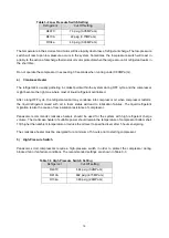
Table 3-2 Low Pressure Switch Setting 

Refrigerant 

Cut-Off setting 

R407C 

7.3 psig (0.05MPa G) 

R410A 

22 psig (0.15MPa G) 

R134a 

4.3 psig (0.03MPa G) 

 
The temperature in the scroll set and motor will rise rapidly due to loss of refrigerant charge. The low-pressure 
switch will react upon low pressure occurs in the system. Sometimes, the low-pressure switch will react in 
priority to the action of discharge thermostat or motor protector when the large amount of refrigerant leaks in 
the short time. 
 
Do not operate the compressor in exceeding 30 seconds when running under 0.03MPa (G). 
 

4) 

Crankcase Heater   


The refrigerant is usually gathering in coldest point within the system during OFF cycle


and the compressor 

might become the right one where most of liquid refrigerant centralized. 
 
After a long OFF cycle, the refrigerant vapor may condense into compressor oil, when compressor restarts. 
the  liquid  refrigerant  mixed  with  oil  in  foam  status  will  lead  to  lubrication  failures.  The  liquid  refrigerant 
migration is also the cause of low insulation resistance of compressor.     

Panasonic  recommends  crankcase  heaters  should  be


used  for  the  system  with  high  refrigerant  charge 

volume. The crankcase heater of suitable power should remain the temperature of compressor bottom shell 
11K higher than ambient temperature or reduce the oil level to specified level after 5 hours energizing. 

The crankcase heater must be energized for a minimum of 5 hours prior to starting compressor. 
 

5) 

High-Pressure Switch 


Panasonic  scroll  compressors  require  a  high-pressure  switch  in  order  to  protect  the  compressor  during 
blocked fan or fan failure conditions. The recommended settings are shown in Table 3-3 
 

Table 3-3 High Pressure Switch Setting


Refrigerant 

Cut-Off setting 

R407C 

464 psig (3.2MPa G) 

R410A 

602 psig (4.15MPa G) 

R134a 

348 psig (2.4MPa G) 


Summary of Contents for 4CW056MA01

Page 1: ...Ver 202203 Horizontal Scroll Compressors Application Manual Panasonic Appliances Compressor Dalian Co Ltd ...

Page 2: ...ator 6 2 7 Discharge Line Check Valve 7 2 8 Suction Line Strainer 7 2 9 Dryer 7 2 10 Oil separator 7 2 11 System Charge Limit 8 2 12 Oil level of the compressor 8 2 13 Operating Envelope 8 2 14 Pipe surface stress 9 2 15 Allowable incline 9 2 16 Vibration 9 3 0 Electrical Parts and Controller Design Considerations 10 3 1 Selection of Electrical Wiring 10 3 2 Selection of Inverter Driver 12 3 3 Sta...

Page 3: ...y and Manufacturing Process Considerations 17 4 1 Removing Rubber Plug 17 4 2 Compressor Mounting 17 4 3 Residual Moisture 17 4 4 Tube Brazing 18 4 5 Leakage Test 20 4 6 Evacuation 20 4 7 Refrigerant Charge 20 4 8 Wiring Connections 20 4 9 Terminal cover and clip 21 4 10 Preliminary Running 22 4 11 Start Compressor with Balanced Pressure 22 4 12 Servicing Scroll Compressors 22 4 13 Other Precautio...

Page 4: ...power before servicing Install the cover of terminal box before energized EXPLOSION OR FIRE HAZARD Remove the refrigerant before brazing operation Do not compress air or energize the compressor under vacuumed condition Use only approved refrigerants and refrigeration oil PERSONAL INJURY Personal safety equipment must be used BURN HAZARD Do not touch the compressor when it is running or stopping un...

Page 5: ...ating Characteristics Panasonic C SW series scroll compressors are designed with fixed eccentric and floating orbit scroll sealing resulting in low sound level and minimal gas leakage and therefore excellent efficiency The Figure 1 2 below describes the scroll compression process First orbit SUCTION gas enters at the perimeter of the scroll elements and is sealed as the scrolls rotate approximatel...

Page 6: ...he reliability the specified designed premium quality refrigerant oil is used in the compressor The refrigerant oil containing foam suppressor has the excellent thermal stability and high durability for overload conditions 1 4 1 Oil Type Each type of refrigerant oil is specially designed for certain types of refrigerant and operating conditions if additional oil charge is added in the field Only s...

Page 7: ...mpressor Models and Motor Type AC Inverter COMPRESSOR with Induction motor ARI Condition Ref HP New Model Former model Disp Input Voltage Capacity kW IP Rating Comment cm3 rev 60rps 90rps R407C 5 4CW056MA01 C SWS180H01C 55 7 200V 12 9 18 0 IP67 Annular legs 7 4CW074NA01 C SWS225H00C 74 4 400V 16 5 23 0 IP67 Annular legs 7 4CW074MA01 C SWS225H01C 74 4 200V 16 5 23 0 IP67 Annular legs 7 4CW074MA11 C...

Page 8: ...wer than recommended pressure Same The tested pressure is approximately same as recommended pressure a Too big of compressor size b Too small of compressor size c Too high of dry bulb temperature in the condenser side Excessive refrigerant has charged in the system Uneven refrigerant distribution in the circuits of condenser Too low rotation speed of condenser fan d Too low wet bulb temperature in...

Page 9: ... 2 5 Liquid refrigerant flood back Liquid refrigerant flood back can cause great influence to the reliability of compressor When liquid compression knocking noise current surge or undesirable vibration etc occurs implement the following countermeasures to prevent liquid refrigerant flood back 1 Add suction accumulator 2 Decrease refrigerant charge amount 3 Change the operation mode 4 Install an in...

Page 10: ...umulator with screen the strainer will not be required 2 9 Dryer A suitable sized filter dryer should be used to ensure the low degree residual moisture level in the refrigerating circuit the molecular sieves type is recommended 2 10 Oil separator An oil separator is recommended to separate a major part of oil from compressor discharge gas and return it directly to compressor crankcase The functio...

Page 11: ...e foaming portion as oil level Low oil level will cause lack of lubrication to rotating parts and seriously affect the compressor reliability Observe the oil level with the compressor with sight glass supplied by Panasonic and consult your account representative for the result Example showed the oil level to keep Figure 2 2 2 13 Operating Envelope The operating envelopes of inverter compressors de...

Page 12: ... incline shall not be more than 10 during operation 2 16 Vibration Since C SW series compressors are designed with high back pressure shell the oil level inside of crankcase is more stable during operation The installation direction of the compressor could be perpendicular or parallel to the running direction of the vehicle Initial operation test for the system at full range of speed must be condu...

Page 13: ... started b Starting Voltage The voltage applied to compressor terminals when compressor is being started When compressor is starting the big starting current will cause the drop of voltage It will be very hard to start compressor if the starting voltage is too low c Running Voltage The line voltage applied to compressor terminals when compressor is running stably This running voltage is a little l...

Page 14: ...x 2 0 2 0 2 0 3 5 5 5 8 0 2 0 30max 3 5 5 5 14 0 40max 3 5 5 5 8 0 50max 8 0 14 0 22 0 60max 5 5 70max 3 5 8 0 14 0 3 5 80max 22 0 30 0 90max 14 0 100max 8 0 38 0 110max 120max 5 5 22 0 30 0 140max 14 0 50 0 5 5 160max 22 0 180max 38 0 60 0 8 0 200max 8 0 30 0 220max 50 0 80 0 240max 14 0 CAUTION OF GROUNDING The internal motor protector cannot protect the compressor against all possible failures ...

Page 15: ... from high frequency operation to avoid frequent fluctuations Compressor smoothly operation depends on a certain voltage input the higher the speed the higher the voltage required During the operation when the output voltage of the inverter is low it should reduce the frequency and limit the compressor from high frequency operation to avoid stall and shutdown of compressor 5 Electromagnetic noise ...

Page 16: ...termined after confirmation of compressor oil level liquid back and reliability If there is a specific description in the compressor specification follow the contents 3 7 Defrost operation Inverter compressors shall operate at low speed right before the start of defrost cycle and right before the end of defrost cycle This will enable the oil to be retained in the compressor To check oil return per...

Page 17: ... the proper compression ratio of compressor Figure 3 4 3 11 On off cycle The on off cycle of compressor shall not be more than 6 cycles per hour The compressor should be operated continuously at least for 5 minutes after being turned on Allow a minimum of 3 minutes shut off time before restarting Or restart the compressor after the pressure difference between high side and low side balances 3 12 R...

Page 18: ...three phase systems mechanic device or reverse rotation module in the system control unit is necessary in preventing three phases compressor from running in the reverse rotational direction 2 Discharge Gas Thermostat The discharge temperature will rise rapidly if the compressor is running under the overload conditions or lack of refrigerant conditions The maximum discharge temperature should be ma...

Page 19: ...rigerant vapor may condense into compressor oil when compressor restarts the liquid refrigerant mixed with oil in foam status will lead to lubrication failures The liquid refrigerant migration is also the cause of low insulation resistance of compressor Panasonic recommends crankcase heaters should be used for the system with high refrigerant charge volume The crankcase heater of suitable power sh...

Page 20: ...r from which the discharge sound cannot be heard when removing rubber plugs 4 2 Compressor Mounting In mobile applications for the consideration of tubing reliability it is important to minimize the motion of compressor during operation The mounting accessories grommets and sleeves that are supplied or specified by Dalian Panasonic should be used as shown in Figure 4 1 The upper mounting rubber ru...

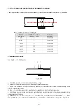
Page 21: ...terial is also acceptable for copper brazing See Table 4 1 for recommended brazing materials Table 4 1 Recommended Brazing Material Metal Silver JIS Code Brazing Temp JIS standard Copper to Copper 4 8 5 2 BcuP 3 720 815 Z 3264 Copper to Steel with copper coated 35 BAg 2 700 845 Z 3261 Copper to Steel Steel with copper coated to steel Steel to Steel 45 BAg 1 620 760 Z 3261 4 4 2 Nitrogen purge Duri...

Page 22: ...ed torch is recommended during brazing b Clean the compressor tubing and system piping prior to assembly c Apply heat to Area 1 moving the torch up down and around the tube in order to heat it evenly It will become dull orange in color d Move the torch to area 2 until it reaches dull orange in color and heat that area evenly e Add braze material to the joint while moving the torch around the joint...

Page 23: ... confirm the vacuum degree of the system after removing the vacuum pump from the system Sufficient vacuum degree means 30 seconds after removing the vacuum pump below 1 0Torr 24 hours after removing the vacuum pump below 7 6Torr Please select proper size of vacuum pump according to the above vacuum degree requirements Do not use compressor as a vacuum pump and NEVER energize the compressor under v...

Page 24: ...monitor can be applied to ensure correct rotation when power is initiated Each compressor is labeled with the appropriate sequence As showed in wiring diagram the line phases R L1 S L2 and T L3 should be connected to terminals U V and W respectively Figure 5 4 Compressor Terminal 4 9 Terminal cover and clip The terminal cover and clip should be installed prior to operation of the compressor To ens...

Page 25: ... the compressor is functioning properly 1 Voltage of the unit should be measured and verified as correct 2 An evaluation of the electrical system should be performed next The motor should be checked by using continuity and short to ground testing The internal motor protector should be given time to reset if a continuity break is found in the motor windings External breakers and associated wiring s...

Page 26: ...e all refrigerant has been evacuated using the procedure above in 4 12 2 If there is still refrigerant in the system this when combined with the compressor oil can ignite if it comes in contact with a flame 1 Use the suitable welding machine or tools to remove the connecting pipes screws flanges or service valves 2 Check the oil in failed compressor If oil is in black color the normal color of oil...

Page 27: ...replace both the liquid line and suction line filter dryers 4 12 6 Returning Failure Compressor 1 The failure compressor should be sealed on suction tube and discharge tube to prevent the refrigerant oil flowing out during transportation 2 Please record the following items in a list Compressor Model Manufacturing Series Number Air conditioning Model and Air conditioning Manufacturing Number Failur...

Page 28: ...e of breaker Refrigerant circuit High pressure side blockage Low pressure side blockage Electrical components Failure of contactor rapid fluctuation or contacts welded Temperature controller Temperature controller trips Compressor Abnormal line voltage Motor winding overheating due to lack of phase Motor winding overheating caused by unbalanced voltage Motor winding overheating caused by loss of r...

Page 29: ...or blockage of condenser coil Short air cycle Low discharge pressure Insufficient refrigerant in system Leakage of refrigerant Too low ambient temperature Large air flow through condenser Liquid refrigerant flooding back Worn compressor High suction pressure Too high of heat load Poor heat insulation Too low superheat setting of expansion valve Malfunction of expansion valve Incorrect installation...

Reviews: