background image

DigitalFlow™ GF868 Service Manual (1 and 2-Channel)

iii


Information Paragraphs

Note:

These paragraphs provide information that provides a deeper understanding of the situation, but is not 

essential to the proper completion of the instructions.

IMPORTANT:

These paragraphs provide information emphasizing instructions which are essential to proper setup of 

the equipment. Failure to follow these instructions carefully may cause unreliable performance.

Safety Issues

Auxiliary Equipment

Local Safety Standards

The user must make sure that he operates all auxiliary equipment in accordance with local codes, standards, 

regulations, or laws applicable to safety.

Working Area

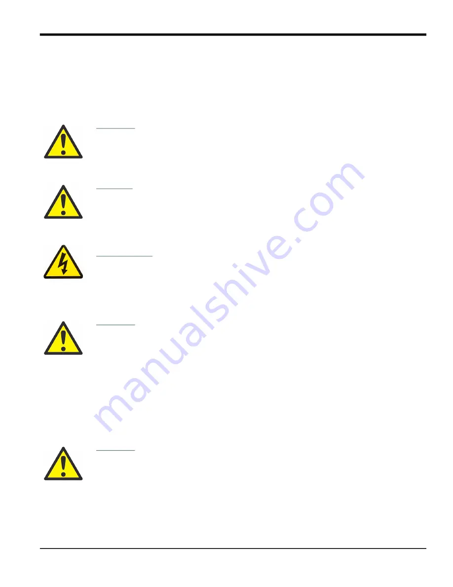
WARNING!

Indicates a potentially hazardous situation which can result in serious personal 

injury or death, if it is not avoided.

CAUTION!

Indicates a potentially hazardous situation which can result in minor or moderate 

injury to personnel or damage to the equipment, if it is not avoided.

HIGH VOLTAGE!

This symbol indicates the presence of high voltage. It calls your attention to 

situations or operations that could be dangerous to you and other persons operating the 

equipment. Read these messages and follow the instructions carefully.

WARNING!

It is the responsibility of the user to make sure all local, county, state and national 

codes, regulations, rules and laws related to safety and safe operating conditions 

are met for each installation.

WARNING!

Auxiliary equipment may have both manual and automatic modes of operation. As 

equipment can move suddenly and without warning, do not enter the work cell of 

this equipment during automatic operation, and do not enter the work envelope of 

this equipment during manual operation. If you do, serious injury can result.

Summary of Contents for GF868

Page 1: ...panametrics com Flow 910 194S Rev F Jul 2021 DigitalFlow GF868 Ultrasonic Flowmeter for Flare Gas Service Manual 1 and 2 Channel...

Page 2: ......

Page 3: ...ore registered trademarks of Baker Hughes Company and its subsidiaries in one or more countries All third party product and company names are trademarks of their respective holders DigitalFlow GF868 U...

Page 4: ...ii no content intended for this page...

Page 5: ...r death if it is not avoided CAUTION Indicates a potentially hazardous situation which can result in minor or moderate injury to personnel or damage to the equipment if it is not avoided HIGH VOLTAGE...

Page 6: ...ipment that you bought has required the extraction and use of natural resources for its production It may contain hazardous substances that could impact health and the environment In order to avoid th...

Page 7: ...uency Outputs 13 1 7 1 Accessing the Calibration Menu 14 1 7 2 Entering Frequency 14 1 7 3 Entering Pulse Number 14 Chapter 2 Error Codes and Screen Messages 2 1 Introduction 17 2 1 1 E0 No Error 18 2...

Page 8: ...Appendix A Service Record A 1 Introduction 39 A 2 Data Entry 39 Appendix B Optional Enclosures B 1 Introduction 41 B 2 Rack Mount Enclosure 41 B 3 Rack Mount Fuse Replacement 42 B 4 Rack Mount Option...

Page 9: ...e x is a number from 0 6 See Chapter 1 Installation of the Startup Guide for a complete description of the available option cards and the procedures for wiring them 1 2 Menu Map The Calibration Menu i...

Page 10: ...ull scale values for each output must be calibrated After calibrating the outputs which have a resolution of 5 0 A 0 03 full scale their linearity should be tested Note The zero point of the analog ou...

Page 11: ...the desired slot The option bar will include a slot listing for each installed option card 3 Press Fx to select the desired output IMPORTANT The procedure for calibrating all the outputs is the same H...

Page 12: ...d within 5 0 A of the 4 mA setting contact the factory for assistance 1 3 3 Calibrating the High End of the Output Range 1 Press F2 to calibrate the high end of the output range 2 Press F1 or F2 to ad...

Page 13: ...are not within 5 A of the values listed in Table 1 above check the accuracy and wiring of the ammeter Then repeat the low and high end calibrations If the analog output still does not pass the linear...

Page 14: ...ependent calibrated current source is not available one of the Slot 0 analog outputs may be used for the calibration During the analog input calibration the Slot 0 analog output will supply the low re...

Page 15: ...ed option card 3 Press Fx to select the desired input The procedure for calibrating Input A is identical to that for calibrating Input B However when calibrating Input B be sure a calibrated current s...

Page 16: ...rrently selected analog input as shown in Figure 3 on page 6 2 Press F1 to store the current 4 mA value or press F2 to cancel the entry In either case the ANALOG INPUT prompt reappears 3 Press F4 to p...

Page 17: ...5 2 Probe Option F1 3 Press F1 to select Input A or F2 to select Input B 1 5 2 1 Set Point Temperature 4 Press F1 to enter the set point temperature formerly known as the zero point This temperature...

Page 18: ...mming Manual The RTDs Submenu to obtain point values at your set point and slope point 1 Press F1 to select Input A or F2 to select Input B 1 5 3 1 Set Number 2 Press F1 to enter the set number former...

Page 19: ...ption card includes three alarm relays which are designated as A B and C To test the alarm relays connect an ohmmeter to the option card terminal block as shown in Figure 4 Refer to the menu map in Fi...

Page 20: ...o the desired normally open or normally closed contact of the currently selected relay See Figure 4 on page 11 for the correct pin numbers on the option card terminal block 4 Pressing F1 CLOSE should...

Page 21: ...nsion slots Each option card includes four outputs which are designated as A B C and D To test the outputs connect a frequency counter to the card s terminal block as shown in Figure 5 Refer to the me...

Page 22: ...T key Verify that the frequency counter reads the correct value 1 7 3 Entering Pulse Number 5 Enter a new frequency in the range of 1 10 000 Hz and press the ENT key Verify that the frequency counter...

Page 23: ...NG F3 F4 TEST EXIT F1 F2 4 mA 20 mA F3 F4 Numer STORE F1 F2 A B Slot x Outputs ANALOG OUTPUT F1 F2 UP DOWN F1 ABORT Analog Outputs Full Scale Numeric CALIBRATING F3 F4 C D F4 F1 20 mA EXIT F1 F3 aLOW...

Page 24: ...Chapter 1 Calibration DigitalFlow GF868 Service Manual 1 and 2 Channel 16...

Page 25: ...troubleshooting process All of the possible Model GF868 error code messages are discussed in this chapter along with the possible causes and the recommended actions When an error code is generated it...

Page 26: ...e Incorrect programming of the path length Loss of signal so that noise at the start of the window is triggering the measurement Action Verify programming of the path length Check for loss of signal 2...

Page 27: ...t Error Problem The current in the analog output circuit exceeds the limits for the analog output port Cause The output load exceeds the specified limits for the analog output port Action Make sure th...

Page 28: ...larger measurement units or a shorter time interval for the current measurement parameter For example choose KSCF M instead of SCF M See Chapter 2 Initial Setup of the Startup Guide for instructions 2...

Page 29: ...log or entering a new name 3 printing a log there are no logs to print 4 displaying a log there are no logs to display Hit any key to resume taking measurements All Sites Cleared hit key This message...

Page 30: ...h P is less than the axial dimension L Enter a new value for L range is X XX to X XX When in the User Program this message indicates that the entered number is unacceptable Hit any key and enter a num...

Page 31: ...ical problems The Diagnostics Menu may only be entered from the Big or Dual measurement mode display See Chapter 2 Displaying Data in the Programming Manual for instructions on setting the display scr...

Page 32: ...eltaT usec Displays the difference in sec between upstream and downstream transit times N A 10 000 nsec Tot K K Re MultiK KFactor Displays combination of all K factors N A N A PEAK PEAK Displays the p...

Page 33: ...tic Menu indicates a possible flowcell problem proceed with this section Flowcell problems fall into two categories gas problems pipe problems Read the following sections carefully to determine if the...

Page 34: ...ed problems may result either from a failure to observe the installation instructions as described in the Startup Guide or from improper programming of the meter By far the most common pipe problems a...

Page 35: ...Any transducer damaged in this manner must be replaced Contact the factory for information on transducers in materials suitable for the application 3 INTERNAL DAMAGE An ultrasonic transducer consists...

Page 36: ...Chapter 3 Diagnostics 28 DigitalFlow GF868 Service Manual 1 and 2 Channel no content intended for this page...

Page 37: ...aker The disconnect device must be marked as such clearly visible directly accessible and located within 1 8 m 6 ft of the Model GF868 The power cord is the main disconnect device An aluminum shroud o...

Page 38: ...use will be ejected from the fuse holder 4 Replace the defective fuse with a new one of the same rating and type Use only 1 1 4 x 1 4 Slo Blo fuses having a rating as indicated in Table 4 and on the w...

Page 39: ...ted circuit board remove the two screws or standoffs along the bottom edge of the printed circuit board Note For an LVD compliant meter with the clear plastic shroud over the electrical connectors the...

Page 40: ...n the notches at the upper right and lower left corners of the socket Gently pry the EPROM up a little at a time at each notch until it comes free 4 Make sure that the beveled corner on the new EPROM...

Page 41: ...lastic snap rivets or metal hardware in some older meters In either case they may be discarded as new plastic snap rivets will be provided 3 There are six 32 pin option card sockets J41 J46 on the rea...

Page 42: ...the two right side mounting studs and install the display shroud over the mounting studs The top and bottom edges of the shroud are bent at a 90 angle to the main surface and these edges must face inw...

Page 43: ...r backlight cable to socket J2 on the left edge of the printed circuit board This plug is polarized so that it can only be installed in the proper orientation with the black wire above the red wire 6...

Page 44: ...listed in Table 5 To purchase the parts listed in Table 5 above or any items not listed in the table contact the factory for assistance To make sure the proper components are obtained be sure to speci...

Page 45: ...Shroud Display Cable Keypad Cable Backlight Cable Mounting Screw 8 places Main Shroud Option Cards Fuse Holder Cap Card Guide Metal Bracket Main Shroud Option Card Socket Metal Bracket Fasteners Optio...

Page 46: ...Cable J2 Connector PC Board Ground Wire Screws or Standoffs Short Standoff 3 places Vertical Components Long Standoff 3 places Metal Bracket Option Card Connectors Fasteners typ Display Connector J52...

Page 47: ...F868 flowmeter the details of the service should be recorded in this appendix An accurate service history of the meter can prove very helpful in troubleshooting any future problems A 2 Data Entry Reco...

Page 48: ...Appendix A Service Record 40 DigitalFlow GF868 Service Manual 1 and 2 Channel Table 6 Service Record Date Description of Service Performed By...

Page 49: ...ecific to that unit Note For compliance with the European Union s Low Voltage Directive this unit requires an external power disconnect device such as a switch or circuit breaker The disconnect device...

Page 50: ...ut 3 Replace the defective fuse with a new one of the same rating and type Use only 5 x 20 mm Slo Blo fuses having a rating as indicated in Table 7 and on the rear panel label 4 Reinstall the black pl...

Page 51: ...th the socket and that the option card is oriented with its external connector positioned in the opening on the rear panel 5 Repeat steps 3 and 4 to install any additional option cards 6 Place the met...

Page 52: ...on all four corners gently press the EPROM into the socket until it is fully seated Do not strike the EPROM or apply excessive force during this procedure 5 After checking for any loose hardware that...

Page 53: ...e new LCD display assembly over the mounting studs on the front panel and fasten it in place with the four standoffs Make sure that the LCD display assembly is oriented with the cables pointing toward...

Page 54: ...nnectors from the printed circuit board Use a marker to identify pin 1 on the right side keypad side of these connectors Note These connectors should be pulled straight up and off the printed circuit...

Page 55: ...G OUT and TRANSDUCER connectors onto the printed circuit board at the locations indi cated in Figure 11 on page 50 Make sure the marked pin 1 sides of the connectors face the right side keypad side of...

Page 56: ...Appendix B Optional Enclosures 48 DigitalFlow GF868 Service Manual 1 and 2 Channel no content intended for this page...

Page 57: ...alFlow GF868 Service Manual 1 and 2 Channel 49 19 00 483 18 25 464 2 25 57 5 22 133 11 37 289 11 82 300 13 13 333 4 19 106 15 70 399 3 31 84 14 83 377 16 99 432 Fuse Figure 10 Model GF868 Rack Mount E...

Page 58: ...g Output Connector CH1 Transducer Connector CH2 Transducer Connector EPROM U4 PCB Mounting Screw typ Printed Circuit Board Option Card Bracket Option Card Socket typ RS232 Connector Ground Lead Green...

Page 59: ...Message 17 Illustration 17 E EPROM Replacing 32 User Program 32 Error Codes 18 19 20 Error Message Display Screen 17 Expansion Slots 1 F Flowcell Problems Gas 26 Pipe 26 Fuse Holder 30 Rating 30 Repla...

Page 60: ...33 Soundspeed Error E2 18 Gas 26 Spare Parts List 36 Special Input Error E10 20 T Temperature Input Error E8 19 Totalizer Frequency Option Card Testing 13 Totals Overflow Error E14 20 Transducers Corr...

Page 61: ...icular purpose and warranties arising from course of dealing or usage or trade Return Policy If a Panametrics Sensing instrument malfunctions within the warranty period the following procedure must be...

Page 62: ...Warranty 60 DigitalFlow GF868 Service Manual 1 and 2 Channel...

Page 63: ...roof enclosure are not permitted The apparatus must be de energized before opening servicing and conducting any routine maintenance Installation shall be in accordance with the installation instructio...

Page 64: ...85 C and will be remotely mounted for process temperatures exceeding 85 C Markings Markings appear on the instrument label which identifies the product model serial number operating ranges hazardous a...

Page 65: ...N 61326 2 3 2006 EN 61010 1 2012 Overvoltage Category II Other standards Used EN 50014 1997 A1 A2 EN 50018 2000 A1 following the provisions of the 2004 108 EC EMC 2006 95 EC Low Voltage and 94 9 EC AT...

Page 66: ...64 DigitalFlow GF868 Service Manual 1 and 2 Channel no content intended for this page...

Page 67: ......

Page 68: ...and company names are trademarks of their respective holders 910 194S Rev F Customer Support Centers U S A The Boston Center 1100 Technology Park Drive Billerica MA 01821 U S A Tel 800 833 9438 toll...

Reviews: