Chapter 1. Installation
1-27
DigitalFlow™ GC868 Startup Guide (1 and 2-Channel)
2.
Wire the flying leads end of the cable to terminal block
RS232
and connect the
other end of the cable to the personal computer.
After the wiring has been completed, consult the User’s Manual for the external
device to configure it for use with the Model GC868.
1.8.4.2
Wiring the RS485
Interface
Use the optional RS485 serial port to network multiple GC868 flowmeters to a single
computer terminal. Upon request, the standard RS232 port on the GC868 may be
configured as a two-wire, half-duplex RS485 interface, through a device such as the
INMAC Model 800052 RS232-RS422/RS485 converter.
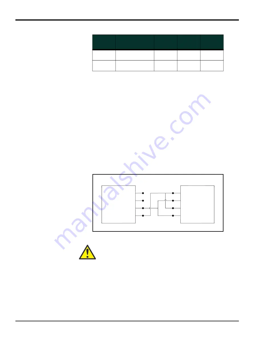
To wire the RS485 serial port, refer to Figure 1-42 on page 1-43 and complete the
following steps:
1.
Disconnect the main power to the unit and remove the cover.
2.
Install the required cable clamp in the chosen conduit hole on the side of the
electronics enclosure.
3.
Feed one end of the cable through the conduit hole, wire it to terminal block J1
and secure the cable clamp. Connect the other end of the cable to the
converter, as shown in Figure 1-36 below.
Figure 1-36: Typical RS485 Connections
4.
If wiring of the unit has been completed, reinstall the plastic shroud, close the
cover on the enclosure and tighten the latches.
5.
Connect the converter to the control system, as described in its User’s Manual.
4
DTR (Data
Terminal Ready)
20
5
3
5
CTS
(Clear to Send)
5
20
8
Table 1-4: RS232 Connection to DCE or DTE Device
RS232
Pin #
Signal
Description
DCE
DB25
Pin #
DTE
DB25
Pin #
DTE
DB9
Pin #
ATTENTION EUROPEAN CUSTOMERS! To meet CE Mark requirements,
all cables must be installed as described in Appendix A, CE Mark
Compliance.
NC 6
NC 7
RX 8
TX 9
1 TD OUT
2
3
4 RD IN
GC868
Converter


