Panamax M5510 Owner'S Manual Download Page 8

FEATURE DETAILS

6

1690 Corporate Circle, Petaluma, CA 94954  •  www.panamax.com

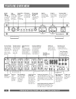
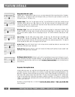
Diagnostic/Indicator Lights

The MAX

®

5510 is loaded with special features to save your connected equipment from many different forms of dangerous

power disturbances.  Five diagnostic lights on the front panel inform you in the event of a power disturbance or when a spe-
cial feature is activated.  The indicators are: 

Switched Outlets:

Green LED.  This light indicates the status of the “Switched Outlets” pushbutton on the front panel and

corresponds with the switch position.  When the button is in the “ON” position, the light is ON.  When the button is in the
“OFF” position, the light is OFF.  “Switched Outlets” refers to the Isolation Transformer Outlets and the High-Current Outlets.
See their respective sections for switching options.

DC Voltage Trigger:

Green LED.  This light indicates status of the DC voltage triggers on the back panel of the MAX

®

5510.

The light is ON when a DC voltage trigger is activated and OFF when a DC voltage trigger is not receiving a signal. This light
will also be ON if nothing is plugged into a DC voltage trigger input jack.  This indicates that the DC voltage trigger is being
bypassed.

Unsafe Voltage: 

Red LED.  Under normal voltage conditions, this light stays OFF.  When this light is FLASHING slowly

(once per second), it indicates an undervoltage (<95 VAC) or overvoltage (>137VAC) condition.  When the light is flashing
quickly (4 times per second), it indicates a 10 second recovery period from an under/overvoltage condition.  This light will
flash quickly when the MAX

®

5510 is first plugged into the wall outlet.

Isolated Power:

Green LED.  When this light is ON, it indicates that the Isolated Power Mode has been selected for the

power supply to the digital source components.

Balanced Power:

Green LED.  When this light is ON, it indicates that the Balanced Power Mode has been selected for the

power supply to the digital source components.

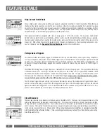
AC Regeneration Control

: Pushbutton switch used for selecting the power supply mode for the digital source com-

ponents connected to the Isolation Transformer Outlet Bank.  One of the adjacent LEDs for Isolated Power or Balanced Power
will illuminate to indicate the active switch position. See the 

Isolation Transformer Outlets

section on the next page for

more information.

Sequential Startup/Shutdown

Complex audio/video systems are susceptible to internally generated surges if all of the system components are powered on
or off at the same time.  One of the symptoms of this condition is speaker “thump” (which can damage the speakers).  The
MAX

®

5510 is designed to eliminate these transients by providing a “start-up” delay for the High-Current Outlets and a “shut-

down” delay for the switched Isolation Transformer Outlets.  This allows the components plugged into the switched outlets
to power-up and stabilize before any amplifiers and powered subwoofers are turned on.  This sequence is reversed during
shutdown.  The amplifiers and powered subwoofers turn off, their power supplies drain, then the equipment plugged into the
switched outlets is turned off.

Information on setting the delay times is included in the

 Isolation Transformer Outlets

and

High-Current Outlet Bank

sections that follow.

Summary of Contents for M5510

Page 1: ...MAX 5510 ACRegenerator Owner s Manual 1690 Corporate Circle Petaluma CA 94954 www panamax com ...

Page 2: ... center that meets the power quality needs for each piece of equipment in your entertainment system This is truly a Firewall for Noise With power this clean you ll wonder how you ever used your system without it Performance alone makes this a world class product but we didn t stop there The understated elegance of the MAX 5510 s styling complements and completes even the most sophisticated Audio V...

Page 3: ...tection 9 AC Power Cord 9 AC Surge Protection 10 SurgeGate Plus Protection 10 Technical Specifications 11 Contacting Panamax 11 Balanced vs Isolated Power 12 Frequently Asked Questions 13 TABLE OF CONTENTS USA Canada 800 472 5555 707 283 5900 Fax 707 283 5901 1 MAX 5510 ACRegenerator 1 RJ 11 Telephone Cable 3 Coax Cables for Satellite TV Cable TV and or Antennas 1 Convenience Lamp with 5W halogen ...

Page 4: ... to you Level 2 for Analog Components The second level in the Tri Power Filtration system features two banks of independently filtered outlets 2 outlets per bank for analog components These outlet banks utilize Balanced Double L filter circuits that are far superior to any other design in filtering out all forms of electromagnetic and radio frequency interference in both common and normal modes Cr...

Page 5: ...USA Canada 800 472 5555 707 283 5900 Fax 707 283 5901 3 CONNECTION DIAGRAM Tri Power Filtration System ...

Page 6: ... optimized for Cable TV or non amplified Rooftop Antenna signal line protection Telephone Jacks In Out connections for telephone line or pay per view line protection Isolation Transformer Circuit Breaker Opens in the event that equipment connected to the Isolated Outlets exceeds 4 amps current draw When white is visible the breaker has opened Reduce the load and push to reset Voltmeter Backlit ana...

Page 7: ...ear panel receptacles at the same time This will overload the lamp s power supply and cause damage not covered by the MAX 5510 s warranty 2 USE ONLY A 12V DC 5W HALOGEN BAYONET BASE ANSI T 3 REPLACEMENT BULB Use USHIO JC12V 5W BA9S or equivalent A higher rated bulb will overload the lamp power supply and cause damage not covered by the warranty 3 Make sure the protruding lamp does not interfere wi...

Page 8: ...dition This light will flash quickly when the MAX 5510 is first plugged into the wall outlet Isolated Power Green LED When this light is ON it indicates that the Isolated Power Mode has been selected for the power supply to the digital source components Balanced Power Green LED When this light is ON it indicates that the Balanced Power Mode has been selected for the power supply to the digital sou...

Page 9: ...lines between the power utility s generating plant and the wall outlet This contaminated power feeds the isolation trans former s primary winding and is regenerated through electromagnetic induction as clean power on the isolated secondary winding The outlets are connected to the secondary winding which has no conductive connection to the primary winding This isolates your digital source equipment...

Page 10: ...gged into a switched outlet on the receiver may also be used if a 12VDC trigger is not built in The MAX 5510 Voltage Sense Trigger input uses standard 3 5 mm mono mini plug jacks These jacks have electrically isolated switches built in If nothing is inserted into the input jacks the voltage sense is bypassed and the MAX 5510 Switched Outlets button on the front panel controls the startup shutdown ...

Page 11: ...V tuners operate at approximately 10 millivolts 0 01 V and utilize the frequency spec trum of 50Mhz to 950Mhz The clamping level of the MAX 5510 s cable TV protection circuitry is 700 millivolts 0 7 volts That s less than 1 volt above normal operating levels The circuitry is shielded to prevent interference and has been opti mized to have less than 1dB of signal loss throughout the entire 50Mhz to...

Page 12: ...ge threshold 95VAC the MAX 5510 will perform the following tasks until line voltage returns to a safe level 1 Disconnects power to all connected equipment 2 Unsafe Voltage LED is activated and will blink once per second during the unsafe voltage condition The MAX 5510 requires line voltage to return to within the safe operating range for 10 seconds before returning to normal operating mode This is...

Page 13: ...CTION UL 1449 Surge Suppression Rating 330V Protection Modes L N L G N G Initial Clamping Level 200V Peak 141V Rms Response Time 1ns Joule Rating 2325 Joules Peak Impulse Current 91 000A Catastrophic Surge Circuit YES AC Line Voltage 120VAC Max Current Rating 15A 1800 Watts Thermal Fuse YES Over Under Voltage Protection YES Over voltage shutoff threshold Response time 137 4 VAC 10 milliseconds Und...

Page 14: ... field radiation from connected power cords through cur rent phase cancellation 1 Radiated electrical fields can still be evident but to a much lesser degree than with grounded neutral power unless the impedances from L G and N G in the connect ed equipment are equal With Balanced Power the asymmetric zero volt N G reference at the panel is replaced by a symmetric ground reference between line and...

Page 15: ...f the lighting is turned ON or OFF If the control knob is turned OFF turn it ON and continue turning until you have reached the desired light level If the control knob is turned ON and there is no light turn the knob to maximum If you still have no light call Panamax Customer Service for help ____ I connected the 5W Convenience Lamp and the lamp will not work What is the problem 1 Check to see if ...

Reviews: