FEATURE DETAILS
6
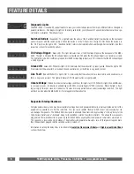
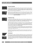
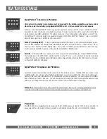
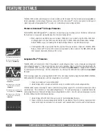
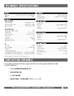
Diagnostic Lights
The MAX
®
5500 is loaded with special features to save your connected equipment from many different forms of dangerous
power disturbances. Five diagnostic lights on the front panel inform you in the event of a power disturbance or when a spe-
cial feature is activated. The indicators are:
Switched Outlets:
Green LED. This light indicates the status of the “Switched Outlets” pushbutton on the front panel
and corresponds with the switch position. When the button is in the “ON” position, the light is ON. When the button is in
the “OFF” position, the light is OFF. “Switched Outlets” refers to the Isolated Outlets and the High-Current Outlets. See their
respective sections for switching options.
DC Voltage Trigger:
Green LED. This light indicates status of the DC voltage trigger on the back panel of the MAX
®
5500. The light is ON when the DC voltage trigger is activated and OFF when the DC voltage trigger is not receiving a signal.
This light will also be ON if nothing is plugged into the DC voltage trigger input jack. This indicates that the DC voltage trigger
is being bypassed.
Ground OK:
Green LED. When this light is ON, it indicates that the wall outlet is properly wired. When the light is OFF,
it indicates that the wall outlet has reversed line and neutral wires, or that there is no ground present.
Line Fault:
Red LED. When this light is ON, it is indicating that the wall outlet has a reversed line and neutral wire, or
there is no ground present. This light will remain OFF if the wall outlet is properly wired.
Unsafe Voltage:
Red LED. Under normal voltage conditions, this light stays OFF. When this light is FLASHING slow-
ly (once per second), it indicates an undervoltage (<95 VAC) or overvoltage (>137VAC) condition. When the light is flash-
ing quickly (4 times per second), it indicates a 10 second recovery period from an under/overvoltage condition. This light
will flash quickly when the MAX
®
5500 is first plugged into the wall outlet.
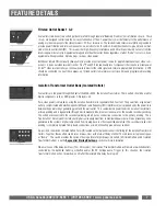
Sequential Startup/Shutdown
Complex audio/video systems may be susceptible to voltage transients generated internally at start-up/shutdown if all of the
equipment is powered on or off at the same time. This can cause speaker “thumps” which are not only annoying but can
also damage the speakers. The MAX
®
5500 is designed to eliminate these transients by providing a “start-up” delay for the
High-Current Outlets and a “shutdown” delay for the switched Isolation Transformer Outlets. This allows the components
plugged into the switched outlets to power-up and stabilize before any amplifiers and powered sub-woofers are turned on.
This sequence is reversed during shutdown. The amplifiers and powered sub-woofers turn off, their power supplies drain,
then the equipment plugged into the switched outlets is turned off.
Information on setting the delay times is included in the
Isolation Transformer Outlets
and
High-Current Outlet Bank
sections that follow.
1690 Corporate Circle, Petaluma, CA 94954 • www.panamax.com


