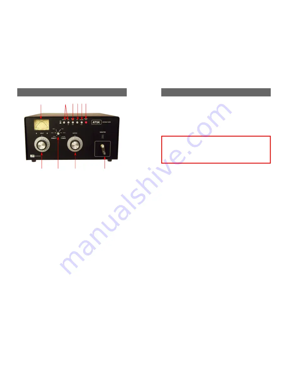
8 Front Panel Description
1. POWER/SWR METER
Dual needle meter displays
FORWARD and REFLECTED power in watts. SWR
is measured where the two needles intersect on the
red scale.
2. PEAK AND PEAK/HOLD
Active circuitry is used to
offer peak reading for SSB. This peak feature is
also translated to provide an approximate 2 second
hold at the peak level for easy viewing. NOTE: The
PEAK/HOLD will function only if the PEAK button is
pressed in as well.
3. RANGE
The power range is 300 watts on low and
3000 watts on high (push button in for high).
4. FAN
The IN position turns on the fan which cools the
internal components of the tuner when using a ser-
vice that requires constant carrier operation (for e.g.
AM or RTTY).
5. BALANCED/COAX
Selects either coax feed or bal-
anced feed. A LED shows when balanced mode is
selected.
1
2
3
7
8
9
10
4 5 6
See Corrections For Balanced/COAX Settings on Page 17
Operating Your AT5K cont’d 13
7. Key your transmitter and adjust the power level for a reading of 100-150
watts on the FORWARD scale. Adjust the INPUT, OUTPUT and INDUC-
TOR controls for a minimum REFLECTED reading while maintaining a FOR-
WARD reading of 100-150 watts using your transmitter power control. Use
the supplied chart of approximate tuning control locations for the different
bands located at the back of the manual.
8. Read the SWR on the red scale at the point where the two needles intersect.
Repeat TUNING the input and antenna controls until the lowest SWR read-
ing is obtained.
This procedure takes patience the first time. The input and an-
tenna controls vary the capacitors and provide fine adjustments.
The roller inductor crank control provides coarse adjustment.
9. When you have tuned your antenna to the best SWR, record the settings of
the INPUT, ANTENNA and INDUCTANCE controls on the chart above for
future reference. When you retune, use these settings as your starting point.
Notes
1. An SWR of 1:1 is best, but an SWR as high as 2:1 may be acceptable. Check
your transmitter/amplifier manual for details.
2. If you cannot get an acceptable SWR, lengthen or shorten your antenna and/
or feedline and retune.
3. Very high or very low impedance loads are to be approached with extra cau-
tion especially when you are going to use high power and the use of an RF
analyzer (e.g. the Palstar ZM30 Antenna Analyzer) would be advisable to
check and understand the kind of load you attempting to use.
4. If you get low SWR readings at more than one setting, use the setting that
gives:
- highest FORWARD power reading
- lowest REFLECTED power reading
- uses the largest capacitance (highest number) on the OUTPUT control.
It is important to remember that consistent with low SWR indicated on the
tuner meter you must have and adjust for the largest capacitance (highest
number) on the output control to keep the losses low and the voltage that
would appear on the antenna capacitor within the 5kV rating;
If you hear a spitting sound while tuning at high power you are probably tun-
ing into an impedance that is on the low side (20
Ω
- 40
Ω
). Please see the
troubleshooting section for more detailed instructions.
CAUTION:
When approaching the end stops of the
roller inductor, (readings of Zero or 229)
SLOW
DOWN
. Slamming the roller wheel into the mechani-
cal end stops on either end of the roller inductor can
damage it.


