Fisher FM-190, Service Manual
The Fisher FM-190 is a premium-quality amplifier that promises high-performance audio. To ensure smooth operation and maintenance, we offer a comprehensive and detailed Service Manual for free download at our website. Visit manualshive.com to access the manual and enhance your experience with this exceptional product.
Share
Download


Reviews:
No comments
Related manuals for FM-190
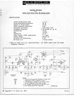
312C
Brand: H.H. Scott Pages: 8
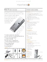
MAX-TV
Brand: Maxfield Pages: 3

Mobile HD
Brand: Scotty Pages: 37

Superchips 3825
Brand: Superchips Pages: 12

nanoStick (73e)
Brand: PCTV Systems Pages: 12

K4500
Brand: Velleman Pages: 24

FineArts M 100-T
Brand: Grundig Pages: 20

DAB22COM
Brand: Wintal Pages: 32

STU-3
Brand: VINCENT Pages: 60

SV130102
Brand: SEVIC Pages: 26

STT 2.0
Brand: SpeakerCraft Pages: 12

SGKT-15
Brand: Dimavery Pages: 2

SGKT-10
Brand: Dimavery Pages: 10


