


Interpreting Status LEDs
18
• Maintaining the Hardware
Palo Alto Networks
Interpreting Status LEDs
This sections describes the device, port, and power supply LEDs that will enable you to determine the
status of these components.
•
“Interpreting the Device LEDs” on page 18
•
“Interpreting the Port LEDs” on page 19
•
“Interpreting the Power Supply LED” on page 20
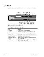
Interpreting the Device LEDs
Figure 9 shows the LED dashboard on the front panel of the PA-5000 Series, and Table 4 describes the
LED functions and states.
Figure 9. Front Panel LEDs
Table 4. Functions and States of the LED Dashboard
LED
State
Description
PWR
(POWER)
Green
The device is powered.
Off
Power is off.
STS
(STATUS)
Green
The device is operating normally.
Yellow
The device is booting up.
HA
Green
This device is the current active device.
Yellow
This device is the current passive device.
Off
High availability (HA) is not enabled on this device.
TEMP
Green
The temperature is normal.
Yellow
The temperature is outside the normal tolerance.
ALARM
Red
There is a hardware failure, which may include power supply detected
but not working, fan failure, Hard drive failure, HA failover, or
temperature above high temperature threshold.
Off
The device is operating normally.
FANS
Green
All fans are operating normally.
Red
One or more fans have failed.
PWR
STS
HA
TEMP
ALARM
FANS
PWR 1
PWR 2
Summary of Contents for PA-5000 Series
Page 1: ...PA 5000 Series Hardware Reference Guide...
Page 14: ...Connecting Power 14 Installing the Hardware Palo Alto Networks...
Page 28: ...Replacing the Fan Tray and Air Filter 28 Maintaining the Hardware Palo Alto Networks...
Page 32: ...Environmental Specifications 32 Specifications Palo Alto Networks...