background image

M-300 and M-700 Appliance Overview

M-700 Appliance Front Panel

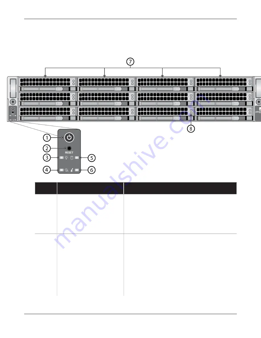
The following image shows the front panel of the M-700 appliance and the table describes each

front-panel component.

Item

Component

Description

1

Power button

Press this button to power on or power off the

appliance. Powering off the appliance with this

button puts the appliance in standby power mode.

To completely power off the appliance, you must

disconnect the AC power cords from both power

supplies.

2

Reset button

Functions identically to the UID button on the

M-300 Appliance Front Panel

.

Use the UID feature to help you locate the

appliance when you move from the front to the

back of the equipment rack where the appliance

is installed. When you push the UID button to

enable the UID feature, both the front-panel

System information LED and the back-panel UID

LED illuminate bright blue to help you locate the

appliance when you move between opposite sides

M-300 and M-700 Appliance Hardware Reference

18

©

2023 Palo Alto Networks, Inc.

Summary of Contents for M-700

Page 1: ...M 300 and M 700 Appliance Hardware Reference docs paloaltonetworks com...

Page 2: ...onetworks com search html Have feedback or questions for us Leave a comment on any page in the portal or write to us at documentation paloaltonetworks com Copyright Palo Alto Networks Inc www paloalto...

Page 3: ...Power to an M 300 or M 700 Appliance 32 Connect AC Power to an M 300 or M 700 Appliance 32 Service the M 300 or M 700 Appliance 33 Replace an M 300 or M 700 Drive 34 Replace an M 300 or M 700 Applianc...

Page 4: ...Table of Contents M 300 and M 700 Appliance Hardware Reference 4 2023 Palo Alto Networks Inc...

Page 5: ...Networks next generation firewall or appliance The following topics apply to all Palo Alto Networks firewalls and appliances except where noted Upgrade Downgrade Considerations for Firewalls and Appli...

Page 6: ...terface for the Data Services service route n a Upgrading a PA 7000 Series Firewall with a first generation switch management card PA 7050 SMC or PA 7080 SMC PAN OS 8 0 and later Before upgrading the...

Page 7: ...ct matches the tracking number that is physically labeled on the box or crate The integrity of the tamper proof tape used to seal the box or crate is not compromised The integrity of the warranty labe...

Page 8: ...d Party Component Support Before you consider installing third party hardware read the Palo Alto Networks Third Party Component Support statement M 300 and M 700 Appliance Hardware Reference 8 2023 Pa...

Page 9: ...and shielded Ethernet cables to ensure agency compliance with electromagnetic compliance EMC regulations French Translation Des c bles Ethernet blind s reli s la terre doivent tre utilis s pour garan...

Page 10: ...the entire fan tray This allows the fans to stop spinning and helps you avoid serious injury when removing the fan tray You can replace a fan tray while the firewall is powered on but you must replac...

Page 11: ...d une barrette d un bus bornes de mise la terre auquel le conducteur lectrode de mise la terre du syst me d alimentation c c est raccord The firewall must be in the same immediate area such as adjacen...

Page 12: ...gauge AWG indiqu et serrez les crous au couple indiqu dans la proc dure d installation de votre pare feu pare feu The firewall permits the connection of the earthed conductor of the DC supply circuit...

Page 13: ...Management mode Panorama Management only mode Panorama Log Collector mode or PAN DB Private Cloud mode M 700 only First Supported Software Release Panorama 10 2 The following topics describe the hard...

Page 14: ...nel System information LED and the back panel UID LED illuminate bright blue to help you locate the appliance when you move between opposite sides of the equipment rack Push the UID button again to de...

Page 15: ...appliance in standby power mode To completely power off the appliance you must disconnect the AC power cords from both power supplies 9 Hard disk drives HDDs Disk drive bays and HDDs used for log sto...

Page 16: ...45 100Mbps 1Gbps 10Gbps Ethernet ports While facing the back of the appliance the ports are labeled as follows The port labels are located on top of the appliance Left Management MGT port used for man...

Page 17: ...computer does not have a serial port use a USB to serial converter Use the following settings to configure your terminal emulation software to connect to the console port Data rate 9600 Data bits 8 P...

Page 18: ...e you must disconnect the AC power cords from both power supplies 2 Reset button Functions identically to the UID button on the M 300 Appliance Front Panel Use the UID feature to help you locate the a...

Page 19: ...source connected to the power supply Solid blue The UID feature is activated see the UID button description for the M 700 Appliance Back Panel 7 Hard disk drives HDDs Disk drive bays and HDDs used fo...

Page 20: ...M 300 and M 700 Appliance Overview Item Component Description Bottom LED Solid red indicates a log drive failure M 300 and M 700 Appliance Hardware Reference 20 2023 Palo Alto Networks Inc...

Page 21: ...second power supply is for redundancy 3 Ethernet ports Two RJ 45 100Mbps 1Gbps 10Gbps Ethernet ports While facing the back of the appliance the ports are labeled as follows The port labels are located...

Page 22: ...ngs to configure your terminal emulation software to connect to the console port Data rate 9600 Data bits 8 Parity None Stop bits 1 Flow control None 7 Unique Identification UID button and LED Use the...

Page 23: ...labeled Ethernet 1 2 The port labels are located on top of the appliance Ethernet 1 2 and Ethernet 1 3 are configured as link aggregation group LAG ports and cannot be changed For information on conf...

Page 24: ...M 300 and M 700 Appliance Overview M 300 and M 700 Appliance Hardware Reference 24 2023 Palo Alto Networks Inc...

Page 25: ...The following topics describe how to install the M 300 and M 700 appliances in an equipment rack and how to connect power to them Install the M 300 or M 700 Appliance in an Equipment Rack Connect Pow...

Page 26: ...EP 1 Attach the inner rail sets two each to each side of the appliance by aligning the square holes on each rail with the rail hooks on the appliance and then sliding the rails toward the front of the...

Page 27: ...clips located at the front and back end of each rail assembly to release the rails from the rack STEP 3 Install the firewall in to the equipment rack by sliding the inner rails in to the outer rack m...

Page 28: ...with washer for each rail Install the M 700 Appliance in a 19 Equipment Rack The following procedure describes how to install the M 700 appliance in a four post equipment rack shipped with the applian...

Page 29: ...on the clip to remove the rail from the appliance STEP 2 Install one outer rack mount rail to each side of the equipment rack Push the two rail hooks on the front and back of each rail in to the squar...

Page 30: ...P 3 Install the appliance in to the equipment rack by sliding the inner rails in to the outer rack mount rails until the appliance stops about halfway in to the rack Push the inner rail release clips...

Page 31: ...liance is flush with the front of the rack The inner rail release clips are shown in step 1 STEP 4 Secure the front of the appliance to the rack by turning the front thumb screws on each rail clockwis...

Page 32: ...iance To avoid injury to yourself or damage to your Palo Alto Networks hardware or the data that resides on the hardware read the Product Safety Warnings STEP 1 Plug two AC power cables provided in to...

Page 33: ...s describe how to replace serviceable components on an M 300 or M 700 appliance Replace an M 300 or M 700 Drive Replace an M 300 or M 700 Appliance Power Supply For information on interpreting the fro...

Page 34: ...determine if it should be replaced contact Palo Alto Networks Support The only difference between replacing an M 300 and M 700 appliance system drive is that the system drive on an M 300 appliance is...

Page 35: ...le and gently pull the handle toward you to remove the carrier and drive The following image shows an M 700 system drive the M 300 system drive is similar STEP 3 Remove the replacement drive from the...

Page 36: ...cement drive with the connectors facing the same direction 2 Remove the four screws that hold the failed drive in the carrier and remove the drive from the carrier 3 Install the replacement drive in t...

Page 37: ...ce configuration Device Operations Configuration Management For information on configuring management access on an M Series appliance refer to Perform Initial Configuration of the M Series Appliance i...

Page 38: ...rational command and viewing the status and model fields admin hostname show system raid detail For example the following output shows that disk drive A2 failed and the drive model is ST8000NM0055 1RM...

Page 39: ...ue to Step 5 If the replacement drive is a different model number than the drive that you removed then continue to Step 6 STEP 5 Same model replacement drive only Install a replacement disk drive that...

Page 40: ...ve sync Disk id A2 Present model ST8000NM0055 1RM size 7630885 MB status active sync STEP 6 Different model replacement drive only Install a replacement disk drive that is a different model than the o...

Page 41: ...it in the carrier and then install the second replacement drive in to bay A1 one that is the same model as the new drive you installed in bay A2 6 Add the second replacement drive to the RAID 1 array...

Page 42: ...information LED also blinks red STEP 2 Disconnect the power cord from the failed power supply STEP 3 Grasp the handle on the failed power supply and simultaneously press the release lever to the left...

Page 43: ...n interpreting the front panel system LEDs see M 300 Appliance Front Panel or M 700 Appliance Front Panel descriptions LED Description RJ 45 Ethernet port LEDs LNK Link LED Off No link Green 100Mbps l...

Page 44: ...Service the M 300 or M 700 Appliance M 300 and M 700 Appliance Hardware Reference 44 2023 Palo Alto Networks Inc...

Page 45: ...appliance hardware specifications For feature capacity and performance information refer to the Panorama Datasheet M 300 and M 700 Physical Specifications M 300 and M 700 Electrical Specifications M...

Page 46: ...iance Rack unit 1U Dimensions 1 7 H x 29 D x 17 2 W 4 32cm H x 73 67cm D x 43 69cm W M 700 appliance Rack unit 2U Dimensions 3 5 H x 28 46 D x 17 2 W 8 89cm H x 72 29cm D x 43 69cm W Weight M 300 appl...

Page 47: ...200W AC power supplies the second power supply is for redundancy Input voltage and frequency M 300 and M 700 appliance 100 240VAC 50 60Hz Power consumption M 300 appliance 330W M 700 appliance 486W Ma...

Page 48: ...ty tolerance M 300 and M 700 appliance Operating relative humidity non condensing 8 to 90 Non operating relative humidity non condensing 5 to 95 Airflow M 300 and M 700 appliance Front to back Maximum...

Page 49: ...cifications The following table describes M 300 and M 700 appliance miscellaneous specifications Specification Value Mean time between failures MTBF M 300 appliance 10 years M 700 appliance 8 years M...

Page 50: ...M 300 and M 700 Appliance Specifications M 300 and M 700 Appliance Hardware Reference 50 2023 Palo Alto Networks Inc...

Page 51: ...with the laws and regulations in each country where there are requirements applicable to our products Our products meet standards for product safety and electromagnetic compatibility when used for th...

Page 52: ...an radiate radio frequency energy and if not installed and used in accordance with the instructions may cause harmful interference to radio communications However there is no guarantee that interferen...

Page 53: ...Equipment VCCI which governs radio frequency emissions in Japan The following information is in accordance to VCCI Class A requirements Translation This is a Class A product In a domestic environment...

Page 54: ...M 300 and M 700 Appliance Hardware Compliance Statements M 300 and M 700 Appliance Hardware Reference 54 2023 Palo Alto Networks Inc...

Reviews: