

PWR
IPM
USB
5
3
4
5
6
CONSOLE
STATUS
1
6
2
ALT
ON/OFF
RESET
Ethernet
Cable
RAM DIMs
RJ-45 to
DB-9 Serial Cable
PWR
IPM
USB
5
3
4
5
6
CONSOLE
STATUS
1
6
2
ALT
ON/OFF
RESET
QuickStart Guide
FortiGate-5002FB2
QuickStart Guide
Copyright 2003 Fortinet Incorporated. All rights reserved.
Trademarks
Products mentioned in this document are trademarks.
01-28005-0043-20041111
PWR
IPM
USB
5
3
4
5
6
CONSOLE
STATUS
1
6
2
ALT
ON/OFF
RESET
Connector Type
Speed
Protocol Description
1, 2
(enhanced
ports)
RJ-45
1000Base-T
Ethernet
Copper gigabit connection to 10/100/1000 copper
networks. The ports are enhanced with a Small Packet
Performance (SPP) Co-processor. The SPP significantly
increases the firewall performance of small packets that
are smaller than 512 bytes used by applications such as
web access and email.
3, 4, 5, 6
RJ-45
1000Base-T
Ethernet
Copper gigabit connection to 10/100/1000 copper
networks. The ports are not enhanced with the SPP. Use
these ports for applications supporting larger packet
sizes such as FTP transfers, file copies and
server-based access.
CONSOLE
RJ-45
9600 bps
RS-232
serial
Serial connection to the command line interface.
FortiGate-5002FB2 normal operating LED indicators
LED
State
Description
PWR
Green
The FortiGate-5002FB2 module is on.
STATUS
Green
Normal operation.
Red
The FortiGate-5002FB2 is booting or a fault condition exists.
IPM
Blue
The FortiGate-5002FB2 is ready to be hot-swapped (or card is ready
to be removed from the chassis).
Flashing
Blue
The FortiGate-5002FB2 is changing from hot swap to running mode or
from running mode to hot swap.
Off
Normal operation. The FortiGate-5002FB2 module is in contact with
the backplane of the FortiGate-5000 series chassis.
Ports 1 - 6
Green
The correct cable is connected to the copper 10/100/1000 interface
and the connected equipment has power.
Flashing
Network activity at this interface.
Amber
The interface is connected at 1000 Mbps.
Install the FortiGate-5002FB2 module into a FortiGate 5020, 5050 or 5140 chassis and connect
the network cables. Always wear an ESD wrist strap or ankle strap to avoid static discharges.
NAT/Route mode
In NAT/Route mode, each FortiGate-5002FB2 module is visible to the networks that it is
connected to. All of its interfaces are on different subnets. Each interface that is
connected to a network must be configured with an IP address that is valid for that
network.
You would typically use NAT/Route mode when the FortiGate-5002FB2 module is
deployed as a gateway between private and public networks. In its default NAT/Route
mode configuration, the module functions as a firewall. Firewall policies control
communications through the FortiGate-5002FB2 module. No traffic can pass through
the FortiGate-5002FB2 module until you add firewall policies.
In NAT/Route mode, firewall policies can operate in NAT mode or in Route mode. In
NAT mode, the FortiGate-5002FB2 module performs network address translation
before IP packets are sent to the destination network. In route mode, no translation
takes place.
Transparent mode
In Transparent mode, the FortiGate-5002FB2 module is invisible to the network. All of
its interfaces are on the same subnet. You only have to configure a management IP
address so that you can make configuration changes.
You would typically use the FortiGate-5002FB2 module in Transparent mode on a
private network behind an existing firewall or behind a router. In its default Transparent
mode configuration, the unit functions as a firewall. No traffic can pass through the
FortiGate-5002FB2 module until you add firewall policies.
You can connect up to six network segments to the FortiGate-5002FB2 module to
control traffic between these network segments.
FortiGate-5002FB2 Module
in NAT/Route mode
Route mode policies
controlling traffic between
internal networks.
Internal network
DMZ network
Port 1
192.168.1.99
Port 3
10.10.10.1
192.168.1.3
10.10.10.2
Port 2
204.23.1.5
NAT mode policies controlling
traffic between internal and
external networks.
Internet
PWR
IPM
USB
5
3
4
5
6
CONSOLE
STATUS
1
6
2
ALT
ON/OFF
RESET
Internal network
192.168.1.3
FortiGate-5002FB2 Module
in Transparent mode
192.168.1.2
Management IP
Port 1
Port 2
192.168.1.1
Transparent mode policies
controlling traffic between
internal and external networks
204.23.1.5
(firewall, router)
Gateway to
public network
Internet
PWR
IPM
USB
5
3
4
5
6
CONSOLE
STATUS
1
6
2
ALT
ON/OFF
RESET
Before beginning to configure the FortiGate-5002FB2 module, you need to plan how to integrate
the unit into your network. Your configuration plan is dependent upon the operating mode that you
select: NAT/Route mode (the default) or Transparent mode.
Web-based manager and
Setup Wizard
Using the Setup Wizard you can configure
basic configuration settings by stepping
through the wizard pages and filling in the
information required.
The FortiGate web-based manager is an easy
to use management tool.
Use it to configure the administrator password,
interface addresses, the default gateway
address, and the DNS server addresses. To
configure advanced settings, see the online help and Documentation CD-ROM.
Requirements:
•
An Ethernet connection between the FortiGate-5002FB2 and a management
computer.
•
Internet Explorer version 6.0 or higher on the management computer.
Command Line Interface
(CLI)
The CLI is a full-featured management tool.
Use it to configure the administrator
password, the interface addresses, the
default gateway address, and the DNS
server addresses. To configure advanced
settings, see the
FortiGate CLI Reference
Guide
on the Documentation CD-ROM.
Requirements:
•
The serial connection between the
FortiGate-5002FB2 module and a
management computer.
•
A terminal emulation application (HyperTerminal for Windows) on the management
computer.
Choose between two different tools to configure the FortiGate-5002FB2 module.
QuickStart Guide
FortiGate-5002FB2
Check that the package contents are complete.
To install the FortiGate-5002FB2 module
1. Install the RAM DIMMs into the module by pushing the RAM DIM gently until the
locking mechanism locks down the DIM.
2. Extend the extraction levers on the module.
3. Carefully slide the module into a chassis slot.
The module is seated properly
when it touches the chassis up to the extraction levers.
4. Lock the extraction levers by pushing them towards each other.
5. If power is supplied to the chassis, the FortiGate-5002FB2 module powers on
when the extraction levers are closed.
6. Tighten the mounting knots on the left and right sides of the front panel.
7. The power switch is built-in to the left side extraction lever. Ensure that the
lockdown thumbscrew is tightened to ensure that power is not interrupted.
Checking the package contents
Checking the package contents
1
Installing the FortiGate-5002FB2
2
Planning the configuration
3
Choosing a configuration tool
4
© Copyright 2005 Fortinet Incorporated. All rights reserved.
Trademarks
Products mentioned in this document are trademarks or registered trademarks of their respective holders.
Regulatory Compliance
FCC Class A Part 15 CSA/CUS
8 November 2005
For technical support please visit http://www.fortinet.com.
01-28008-0167-20051108
Refer to the Documentation CD-ROM for information on how to control traffic, and how to configure HA, antivirus protection, Web content filtering, Spam filtering, intrusion
prevention (IPS), and virtual private networking (VPN).
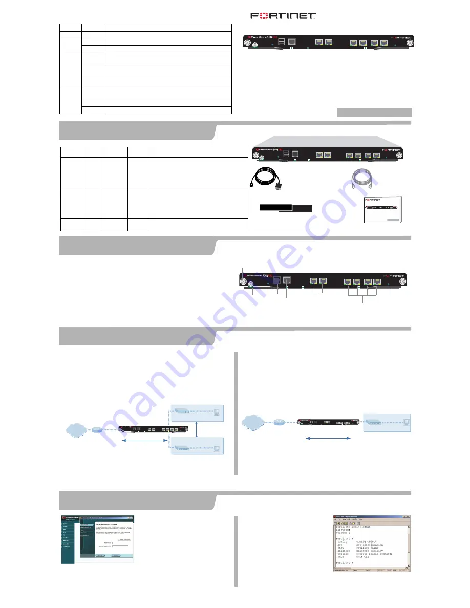
PWR
IPM
USB
5
3
4
5
6
CONSOLE
STATUS
1
6
2
ALT
ON/OFF
RESET
3 4 5 6
10/100/1000 Copper
RJ-45 Serial
Connection
USB
Extraction
Lever
Mounting
Knot
Mounting
Knot
Extraction
Lever
1, 2
10/100/100 Copper
with SSP Co-Processor


