background image

Palo Alto Networks

 Maintaining the Hardware • 

21

Replace a Disk Drive

7.

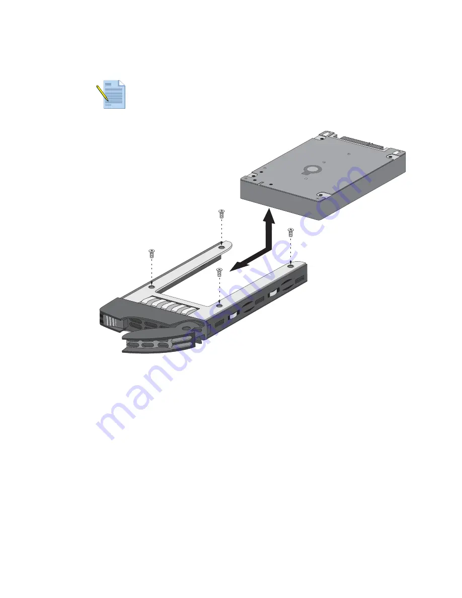
Remove the four screws that hold the drive in the drive bay and then remove the failed 
disk drive as shown in Figure 12. 

Figure 12.   Removing/Installing a Drive from the Drive Bay

8.

Put the new drive in the carrier and attach it to the carrier using four screws as shown in 
Figure 12.

9.

Ensure that the drive bay lever is in the open position; if it is not, press the purple button 
on the drive bay to release the lever and pull it out until it is fully open.

10. Slide the drive bay assembly into the drive slot on the appliance until it is about 1/4” 

from being fully inserted. You can do this by pushing on the purple button, which will 
cause the lever to close part way. After the drive is almost fully inserted, close the lever to 
seat the drive in place as shown in Figure 11.

11. Now that the new drive is installed, add it to the RAID1 pair by running the CLI 

command 

request system raid add <

drive>

. For example, if drive A2 failed in 

the A1/A2 RAID1 pair, you would run 

request system raid add A2

.

12. To check the status of the new drive, run 

request system raid detail. 

In this 

example, drive A2 shows 

spare rebuilding

 as shown in the following output: 

Disk Pair A                           Available
   Status                       clean, degraded
   Disk id A1                           Present
       model        : ST91000640NS

Note:  

If you are using a blank carrier that does not have a drive installed, you may 

have to remove the blank drive insert before installing the new drive.

SA

TA

SAS

SA

TA

SAS

SA

TA

SAS

SA

TA

SAS

Summary of Contents for M-500

Page 1: ...M 500 Appliance Hardware Reference Guide...

Page 2: ...rmation on the additional capabilities and for instructions on configuring the features on the firewall refer to https www paloaltonetworks com documentation For access to the knowledge base complete...

Page 3: ...re You Begin 9 Equipment Rack Installation 10 Rack Mount Procedures 10 Connecting Cables to the Device 17 Connecting Power 17 Chapter 3 Maintaining the Hardware 19 Cautions and Warnings 19 Interpretin...

Page 4: ...4 Table of Contents Palo Alto Networks Chapter 5 Compliance Statements 27 Appendix A General Safety Information 29 Other Regulatory Information 31...

Page 5: ...an M 100 or M 500 appliance in Panorama mode or a Panorama virtual appliance can manage PAN DB Private Cloud mode Functions as a private URL filtering solution that Palo Alto Networks firewalls can us...

Page 6: ...E1 H2 to add up to 8 more drives 4 pairs for a total of 8TB of storage Drive bays I1 to L2 are reserved for future use 2 Drive LEDs Left LED Illuminates red when a drive failure occurs Right LED Flash...

Page 7: ...cables blocking the air vents Blinking red 1Hz Fan failure has occurred Blinking red 25Hz Power failure due to power supply failure or the power cord is not connected to one of the power supplies Sol...

Page 8: ...s Guide 7 0 or later and for information on configuring these ports for PAN DB refer to the PAN OS Administrator s Guide 7 0 or later located on the Technical Documentation Portal Port 3 is reserved f...

Page 9: ...ber provided to you electronically when ordering the product matches the tracking number that is physically labeled on the box or crate The integrity of the tamper proof tape used to seal the box or c...

Page 10: ...ounted device does not cause hazardous conditions due to uneven mechanical loading Circuit overloading Ensure that the circuit that supplies power to the device is sufficiently rated to avoid circuit...

Page 11: ...er rail on the right side of the chassis The inner rails install over the mounting hooks and then slide forward to lock in place The mounting screw holes will be exposed at which time you can use the...

Page 12: ...f the outer rail to adjust the length until the rail fits within the posts of the rack 6 Hang the hooks of the rear portion of the outer rail onto the slots on the rear of the rack Use rack mount scre...

Page 13: ...the chassis into the fully extended position Figure 6 Install the Chassis Into the Rack 10 Simultaneously press the locking tabs on both sides of the rails and push the chassis all the way into the r...

Page 14: ...ng the outer rail until the posts reach the round holes and then evenly pull the outer rail away from the inner rail as shown in Figure 7 Figure 7 Two Post Rail Kit Components Left Inner Rail Right In...

Page 15: ...nd Secure the Front Rail Inner Rail Inner Rail Inner Rail Inner Rail 5 Align the outer rail holes with the inner rail post and push the outer rail into place Then slide it forward until the rack mount...

Page 16: ...r rail threaded post as shown in Figure 9 Figure 9 Outer Rail Outer Rail Cylinder Head Screw Install the Outer Rail to Secure the Chassis to the Rack CAUTION It is important that you secure the outer...

Page 17: ...ribute Panorama or PAN DB traffic load Back Panel Cable Connections Connecting Power To power on the M 500 appliance plug two power cables into grounded wall outlets using separate circuits and then a...

Page 18: ...Connecting Power 18 Installing the Hardware Palo Alto Networks...

Page 19: ...ype Dispose of used batteries according to the battery manufacturer s instructions WARNING Removal of the equipment s top cover is to be done only by Palo Alto Networks trained service person s Interp...

Page 20: ...LED on the drive bay You can also check the drive status by running the show system raid CLI command and viewing the output You will see Disk Pair A and Disk Pair B and the failed drive will show Mis...

Page 21: ...o this by pushing on the purple button which will cause the lever to close part way After the drive is almost fully inserted close the lever to seat the drive in place as shown in Figure 11 11 Now tha...

Page 22: ...l be generated an audible alert will sound and the power failure indicator described in the Front Panel Description on page 6 will change to amber and will flash To replace a failed power supply 1 Ide...

Page 23: ...e Specifications on page 24 Electrical Specifications on page 24 Environmental Specifications on page 24 Physical Specifications Table 4 lists the physical specifications for the M 500 appliance Table...

Page 24: ...ministrator s Guide 7 0 or later and for information on configuring these ports for PAN DB refer to the PAN OS Administrator s Guide 7 0 or later located on the Technical Documentation Portal Port 3 i...

Page 25: ...ications 25 Environmental Specifications System air flow Front to rear Operating humidity 8 to 90 non condensing Storage humidity 5 to 95 non condensing Table 7 Environmental Specifications Continued...

Page 26: ...Environmental Specifications 26 Specifications Palo Alto Networks...

Page 27: ...il for Interference by Information Technology Equipment VCCI which governs radio frequency emissions in Japan The following information is in accordance to VCCI Class A requirements Translation This i...

Page 28: ...28 Compliance Statements Palo Alto Networks...

Page 29: ...y opening the cover of the appliance you may be exposed to a risk of electric shock The components inside the appliance housing should only be serviced by Palo Alto Networks The M 500 appliance should...

Page 30: ...iance is installed in a closed or multi unit rack assembly the operating ambient temperature in the rack environment may be greater than the room ambient temperature Therefore consideration should be...

Page 31: ...customs and export control laws and regulations of the United States U S and may also be subject to the customs and export laws and regulations of the country in which the Products are manufactured a...

Page 32: ...32 Palo Alto Networks...

Reviews: