12
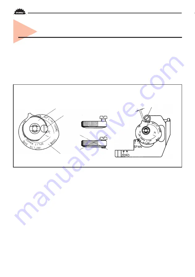
With the cover and indicator removed, loosen the screw 1 and turn the cam locking nut 2
counterclockwise until the cam loosens. Adjust the cam 3 as desired making sure that the
ball bearing 4 always is riding on an active lobe on the cam. To secure the cam, make sure
that screw 1 is backed out from the locking nut 2 then finger tighten the locking nut and
tighten screw 1. Install and adjust the indicator and reinstall cover.
6. Cam adjustment
3
1
correct
incorrect
2
4
1-2 mm (1/16")
Summary of Contents for PMV EP5
Page 1: ...IOM Instructions P4 P5 EP5 alve Control System ...
Page 11: ...11 X Port plugged C1 C2 S C1 C2 S C1 C2 S I I I Direct function ...
Page 27: ...27 Dimensional drawing P4 ...
Page 30: ...30 Spare parts P5 EP5 84 ...
Page 32: ...32 84 Spare parts P5 EP5 ...
Page 34: ...34 18 Certificates Cenelec Atex black label ...
Page 35: ...35 Cenelec Atex black label ...
Page 36: ...36 ...
Page 37: ...37 Cenelec Atex white label ...
Page 39: ...FM White label ...
Page 40: ...CSA White label ...
Page 41: ......


