- 1-
DC INVERTER MONOBLOCK AIR TO
WATER HEAT PUMP AND CHILLER
User Manual
REV:WR-2017V8
Page 1: ...1 DC INVERTER MONOBLOCK AIR TO WATER HEAT PUMP AND CHILLER User Manual REV WR 2017V8...
Page 2: ...ed during installation for heat pump air conditioning side to ensure proper water flow 2 Water filter MUST be installed before water go into PLATE HEAT EXCHANGER The water filter need to be cleaned at...
Page 3: ...s 0 factory setting the auxiliary heater switches on to ensure the heat pump unit works normally The unit is also capable of cooling in the summer The heat pump controller is an intelligent wired syst...
Page 4: ...is led off to a water drain or a suitable soak away The distance between the unit and the exterior wall must be at least 350 mm The free space above must be at least one meter The unit must not be pl...
Page 5: ...all installation options When connecting with the AH9 11 16 the total water volume in the heat pump pipe system and buffer tank must be at least 10 liters per KW of output A Space Heating Cooling DHW...
Page 6: ...Cooling DHW Solar Application 1 Solar Application 2 1 Heat Pump 3 DHW sensor 4 Water filter 5 Ball valve 6 Air discharge valve Tap Water Inlet DHW with solar heating C4 Solar hot water system antifree...
Page 7: ...pe Connection 28mm pipe is recommended The pipe work must be flushed before the heat pump is connected so that any contaminants do not damage the components parts The heating cooling water inlet and o...
Page 8: ...with the power supply there is still a risk of damage due to freezing During the installation Anti freeze Ethylene Glycol is strongly recommended If the air temp is ever lower than 0c it must use enou...
Page 9: ...9 Wiring Diagram 3 Phase 3 4 1 Installation Drawing...
Page 10: ...ver 30 minutes withdraw AC antifreeze When anti freezing if water temperature reduced to 1 C or lower machine will stop and error code Pd display 3 5 COMMISSIONING 3 5 1 Preparations Before commission...
Page 11: ...ed from the hot water and venting may be necessary If bubbling sounds can be heard from the heat pump the circulation pump or radiators the entire system will require further venting When the system i...
Page 12: ...ompressor the auxiliary electric heater E2 will start together with E1 When the heat pump is running AC heating A When the heat pump runs AC heating normally the auxiliary electric heater E2 turns on...
Page 13: ...H water pump or fan motor 13 DHW 14 Sterilization 15 auto mode 16 room heating 17 cooling 18 service icon 19 lock icon 20 Temp 21 Indicating temp location 22 temp unit 23 Defrost icon 24 anti freeze 2...
Page 14: ...ization will fail to work In on or standby mode first press key M and for 3 seconds second press key M 15 icon appears then press the or to set sterilization temperature press key to confirm the numbe...
Page 15: ...y select the setting period press to confirm Hour number flash as below 2 Press up and down key to select number of hour press to confirm After confirmation minute number flash press up and down key t...
Page 16: ...eed 4 4 6 Auto mode icon Automatically select heating or cooling mode After you select AUTO mode when ambient temp 15C it run AC cooling mode When ambient temp 25C it run AC cooling mode When ambient...
Page 17: ...ssor abnormal stop Red and flash compressor stops abnormally F4 outdoor module radiator sensor error Flash 5 time Temp sensor open circuit or short circuit F5 outdoor current sensor error Flash 8 time...
Page 18: ...y only 0 P24 EEV Temp differential to stop the valve heating 5 10 for factory only 0 P25 EEV temp differential to stop the valve cooling 5 10 for factory only 0 P26 water pump working mode 0 no stop 1...
Page 19: ...h a beep parameter reset indoor PCB need to power off and on again to make the change valid parameter reset to default 4 functional parameter P14 When parameter valve 1 when unit working with AC heati...
Page 20: ...2 four way valve 1 on 0 off 23 bypass valve 1 on 0 off 24 1 electrical valve 1 on 0 off 25 2 electrical valve 1 on 0 off 26 3 electrical valve 1 on 0 off 27 1 electrical heater 1 1 on 0 off 28 2 elect...
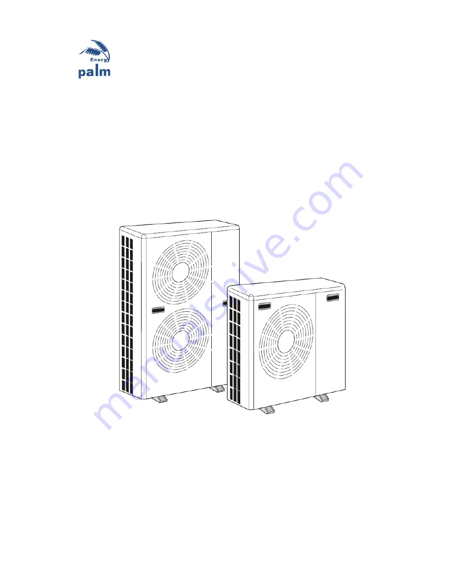
Page 21: ...21 5 1 Internal View 5 2 System Drawing AH9 11 16 17S 25S...
Page 22: ...22 5 3 Dimensions Model 9 W 1090 D 420 H 780 A 440 B 810 16 17S 1280mm for 16 17S 1462mm for 25S...
Page 23: ...has power in the winter whether the unit is used or not 6 2 Maintenance for Specialist 1 Check the power unit and electrical system 2 Check the water system safety valves and exhaust devices are work...
Page 24: ...he same time you could set the water temperature lower This will basically charge your home during the day so in the evening the home is warm and the heat pump simply maintains the heat This is not co...