


system component breakdown and can indicate potential
failure. Discard both the element and its O-rings in
accordance with local Health and Safety Procedures. The
filter element is NOT CLEANABLE. Any attempt to clean
the filter can cause degradation of the filter medium and
allow contaminated fluid to pass through the filter.
7.4 Inspect filter cover assembly (5) and bypass valves
for possible damage or malfunction. Replace filter
cover assembly if damage is observed. Remove any
accumulated dirt from the filter tube interior and cover
assembly being careful to prevent contaminant from
entering the outlet and flowing downstream. DO NOT
run the system without a filter element (8) installed.
Check the O-rings (6) on the cover assembly (5) and
centre post (3) are not damaged. Use the correct
replacement filter element (8) part number called for on
assembly nameplate.
7.5 Lubricate element O-ring seals with clean system fluid
and push filter element (8) straight over the housing
centre post. Ensure the cover assembly (5) and centre
post (3) threads are clean and dry. Lightly lubricate the
centre post threads, O-ring seal and cover assembly
seals with clean system fluid. HAND TIGHTEN cover
handle until cover assembly and tube are in contact.
O-ring sealing is not improved by over tightening.
7.6 Open housing vent plug (10). Open commuter valve
(16) (three full turns max). Slowly open commuter valve
to equalise the pressure between the two sides of the
housing. Close vent plug when bubble free fluid issues
from it. Close commuter valve and check for leaks. Filter
housing is now ready for changeover when required.
Close commuter valve (16).
NOTE: For UR649, UR669 and UR689 units, the above applies
to each housing having elements replaced.
7.8 After element change ENSURE VISUAL DIFFERENTIAL
PRESSURE WARNING DEVICE IS RESET BY
PUSHING IN THE BUTTON; electrical devices are
reset automatically. When system reaches normal
operating temperature, check that electrical switch has
not actuated and/or that visual warning button remains
depressed. If visual indicator rises due to a cold start
condition, reset again as per Section 6.
8
Fluid sampling
Optimum sampling to verify fluid condition can be achieved
by the use of sampling adaptors installed in place of or in
combination with the differential pressure device. This provides
up and downstream 1/4-inch BSP parallel thread ports to be
used for sampling. For more information consult Pall or your
local Pall distributor. Pall offers a fluid contamination analysis
service - consult the Pall sales office.
4
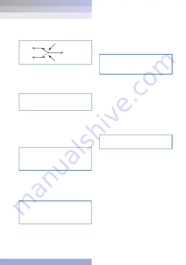
Figure 1
- Switch Circuit Diagram
C or black or
tag 2
A or white
or tag 1
B or red
or tag 3
LOW DIFFERENTIAL PRESSURE
HIGH DIFFERENTIAL PRESSURE
RETURN LINE FILTERS
s e r v i c e
i n s t r u c t i o n s
Athalon
®
UR629/649/669/689 Series
WARNING:
FAILURE TO REPLACE DAMAGED PARTS IN THE
FILTER ASSEMBLY CAN CAUSE COMPONENTS IN
THE HYDRAULIC SYSTEM TO FAIL OR DEGRADE IN
THEIR PERFORMANCE.
WARNING:
DO NOT USE PIPE WRENCH, HAMMER OR ANY
SIMILAR TOOL TO TIGHTEN COVER.
7
Filter element servicing
During servicing, the external surfaces of the filter assembly
must be cleaned to remove any dust deposits.
Servicing must be conducted using suitable tools that do not
present a hazard.
Servicing must not be carried out when a potentially explosive
atmosphere is present.
Refer to Service Parts List (Section 10) for item numbers for
applicable replacement element series. Remove and replace
element as follows:
7.1 Open commuter valve (16) (three full turns max). Crack
open off-line vent plug. Slowly open commuter valve to
equalise pressure in the two sides of the housing. Close
vent plug when bubble-free fluid issues from it. Close
commuter valve (16).
NOTE: Change-over valve handle indicates the filter housing on
stream.
7.2 The off-line housing, now isolated from the system by the
change-over valve, is depressurised by slowly venting
through the vent plug (10). Open drain plug (11) and drain
fluid into a suitable container. Discard fluid in accordance
with local Health and Safety regulations. Close drain plug
(11) and torque tighten to 12 ft/lbor 16 Nm.
NOTE: During element replacement some small internal
leakage may be noted from the on-line filter housing.
7.3 Manually unscrew cover handle and remove filter cover
assembly (5) from tube (2). Remove element (8), if already
fitted, and carefully inspect the surface for significant
visible contamination. Normally no dirt should show but
visible dirt or particles from the filter tube (2) interior
and filter cover assembly (5) can be an early warning of
CAUTION:
Filter elements should be replaced upon indication or
at specified intervals, six months maximum. Failure to
change the element will cause the filter to go on bypass.
WARNING:
FAILURE TO CLOSE THE COMMUTER VALVE AND
TO DEPRESSURISE THE FILTER HOUSING BEFORE
SERVICING THE FILTER ELEMENT COULD RESULT
IN EXPLOSIVE LOSS OF FLUID, DAMAGE TO
EQUIPMENT AND POSSIBLE PERSONNEL INJURY.
WARNING:
DO NOT ATTEMPT TO CLEAN OR RE-USE THE
ELEMENT.
ONLY USE GENUINE PALL REPLACEMENT FILTER
ELEMENTS. USE OF SUBSTITUTE ELEMENTS MAY
INVALIDATE PRODUCT WARRANTY.


