D U P L E X F I L T E R A S S E M B L Y
s e r v i c e
i n s t r u c t i o n s
ENGLISH
(f)
Install O-rings (13, 20) into grooves in head.
(g) Clean all threads before applying Loctite 243 medium
strength to Socket Head Cap Screws (6) and hex bolt
(6.1), install and torque to 50-55 LB-FT.
(i)
Install Filter Element (10) per Section 7.
8.6 Lubricate o-rings and install bleed and drain plugs (5
and 8) and torque to 10-14 LB-FT.
8.7 Commission filter assembly per Section 4.5.
9
Check Valve Servicing
NOTE: Service Check Valve at the same time
as Ball Valve service.
9.1 Completely shut down system and depressurize system
by opening bleed plugs (5) and remove drain plugs (8)
after depresurizing.
9.2 With the ball valve handle shaft facing the operator,
remove the right hand Head Assembly.
(a) Remove Filter Element (10) per section 7.
(b) Remove 4 Socket Head Cap Screws (6) and loosen 1
hex head bolt. Remove head (1).
9.3 Remove Check Valve assembly by pulling straight
out. (11).
9.4 Restrain one of the valve seats and unscrew the
opposite end (see Fig. 8). (DO NOT DAMAGE SEAL
AREA AND DO NOT HOLD ONTO THE SHAFT).
9.5 Remove the poppets.
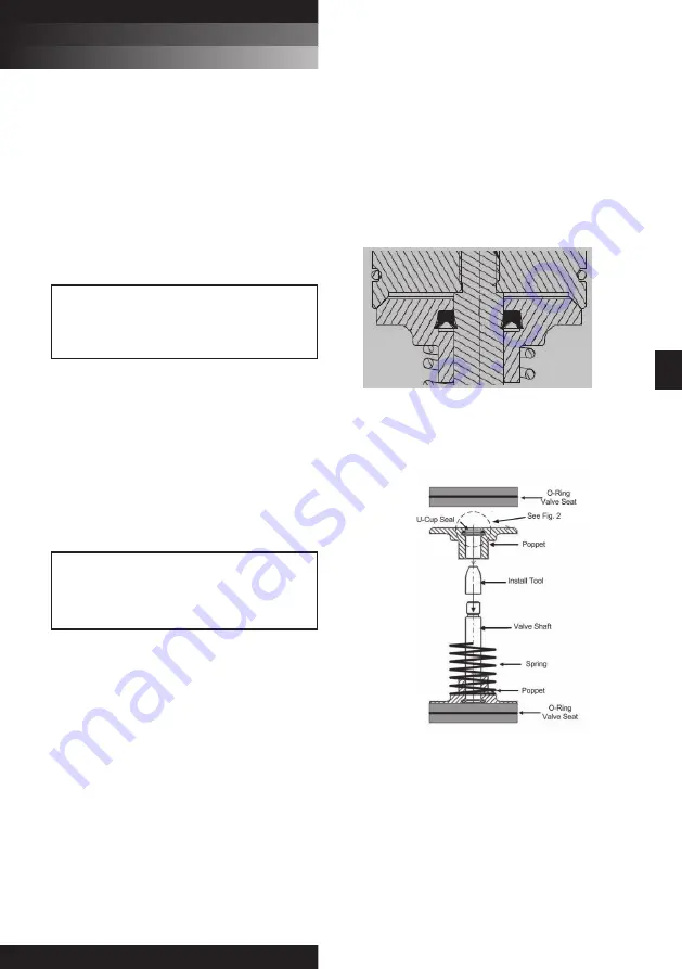
NOTE: Lubricate all seals before installation. The open end of
the U-cup seal must point toward the center of the Check
Valve Assembly. (see Fig. 2)
9.6 Replace O-rings and U-cup seals. Use appropriate kit
per type of seal. See Check Valve Seal Kit list.
(Section 13)
NOTE: Poppets and seats are matched sets. Do not
interchange seats and poppets. See Fig. 3 for proper part
configuration.
9.7 Assemble (per Figure 3.)
NOTE: Use seal installation tool to install new seals and
poppets onto the valve shaft. Failure to use this tool will
damage the U-cup seals.
9.8 Clean all threads before applying removable Loctite 243
to shaft threads and attach removed seat.
9.9 Install Check Valve Assy. (11).
9.10 Install head. Clean all threads before applting Loctite
243 medium strength to Socket Head Cap Screws (6)
and hex bolt (6.1), install and torque to 50-55 LB-FT.
9.11 Install Filter Element (10) per Section 7.
9.12 Lubricate o-rings and install bleed and drain plugs (5
and 8) and torque to 10-14 LB-FT.
9.13 Commission filter assembly per Section 4.7.
5
UR229
UR229 Series
WARNING:
FAILURE TO DEPRESSURISE THE SYSTEM BEFORE
SERVICING UNIT COULD RESULT IN EXPLOSIVE
LOSS OF FLUID. DAMAGE TO EQUIPMENT AND
POSSIBLE PERSONAL INJURY.
WARNING:
THIS ASSEMBLY IS SPRING LOADED. ENSURE
ASSEMBLY IS PROPERLY RESTRAINED DURING
DISASSEMBLY TO PREVENT POTENTIAL FOR
DAMAGE TO PARTS OR POSSIBLE PERSONAL INJURY.
U-Cup Orientation
Figure 2
Check Valve Configuration
Figure 3


