Larisch
93-505_99-04_00-03.doc
A22839,21.03.17
PALFINGER Tail Lifts GmbH
| Fockestraße 53 | D-
27777 Ganderkesee | T + 49 4221 853-0 | [email protected] | www.palfinger.com
Assembly instructions
MBB F 1000 LD
– F 1500 LU; MBB F 1500 L
(former: KFL, 1500 Twinfold)
1. Please check before assembly
1.
Does the delivery correspond with your order?
2.
Is the installation drawing corresponding to the type present?
3.
Does the operating voltage of the loading tailgate correspond with that of the vehicle?
4.
Insofar as there is an attachment proposal present, check that it is correct, and also the vehicle
dimensions and installation drawing.
5.
Is a double floor (wear floor) to be installed?
If yes then set the platform and the HAP higher.
6.
When folding in and out 25 mm finger clearance is required between the platform and the lower
edge of the HAP.
7.
With trailer operation, check for freedom of movement of the drawbar.
8.
It is essential that the vehicle manufacturer's attachment guidelines be adhered to.
Preparatory work on the chassis
Install subframe if required. See vehicle manufacturer's attachment guidelines.
Arrange chassis and subframe in accordance with installation drawing and attachment proposal.
Note !
Special tools such as assembly equipment, installation gauge, coil tester, pressure manometer etc.
can be acquired from
PALFINGER Tail Lifts
on request.
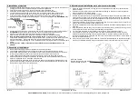
2. Rear connection profile (HAP)
1.
Shorten HAP equally on both sides to suit installation width.
2.
Arrange free space in the loading area for assembly of the HAP, note door seals where necessary.
3.
The HAP forms the end of the loading area.
4.
Install the HAP flush with the load area.
5.
Weld the HAP in accordance with the roll-over weights.
We recommend a bracing of the subframe / chassis frame with strong gusset plates, particularly in
the area of the HAP reinforcing plates.
3. Assembly of loading tailgate with rear connection profile as assembly
equipment
1.
There are assembly holes in the web plates of the HAP.
2 pieces of round steel bar are required Ø28x500 mm long (not part of the
PALFINGER Tail Lifts
delivery).
2.
Bolt on the torsion arms by means of the round bar steel and the assembly holes and check the
side alignment to the installation.
3.
Position the height of the stand in accordance with the installation drawing.
Ensure the largest possible amount of ground clearance and freedom of movement of all parts.
4.
Turn the stand such that the under-ride protection is parallel to the installation.
5.
Fasten the loading tailgate to the vehicle chassis by means of bracket plates, per the installation
drawing and vehicle manufacturer's attachment guidelines.
6.
Remove round bar steel
ATTENTION!
Torsion frame can swing
down as there is not yet
enough oil in the lifting
cylinder.
Flush
Rear connection profile (HAP)
Gusset plates (4 units)
Subframe
Chassis frame
Flush
Flush
Round bar steel
Torsion arm
Parallel brace
Stand tube


