


19
18
MONTAGGIO
/ ASSEMBLY / MONTAGE / MONTAGE / MONTAJE
MONTAGGIO
/ ASSEMBLY / MONTAGE / MONTAGE / MONTAJE
8
3
11
10
9
2
1
6
4
7
5
2
MONTAGGIO
/ ASSEMBLY / MONTAGE / MONTAGE / MONTAJE
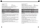
MONTAGGIO PARTI ESTERNE
Inserire gli o-ring (1) nelle rispettive sedi situate all’interno della
piastra (2).
Avvitare manualmente i canotti (3) all’incasso.
Calzare la piastra (2) sui canotti dell’incasso (3), facendo attenzione
a non rovinare la finitura al momento del montaggio, applicare il
silicone sulla piastra e appoggiarla perfettamente aderente al muro.
Posizionare l’inserto (6) sulla cartuccia rubinetto/deviatore (7) e
fissarlo con l’apposita vite (8).
Fissare la maniglia rubinetto/deviatore (9), avvitando con l’apposita
chiave a brugola da 2,5 mm il grano (10) all’interno del rispettivo foro,
situato nella parte posteriore della maniglia.
Inserire il tappino (11) nel foro posto nella parte posteriore della
maniglia.
Posizionare la camma (4) e la maniglia (5) sulla cartuccia
seguendo le indicazioni riportate nella pagina seguente.
EXTERNAL PARTS MOUNTING
Insert the o-ring (1) in its respective place into the holes of the
plate-rose (2).
Screw manually the sleeve (3) to the concealed part.
Fit the plate (2) on concealed part’s sleeve (3), paying attention not
to ruin the finishing when mounting, apply silicone on the plate and
place it perfectly fitted to the wall.
Place the inset (6) on the cartridge faucet/diverter (7) and fix in with
the right screw (8).
Fix the faucet/diverter handle (9), screwing with the right 2,5mm
Allen key the screw (10) inside the right hole, placed on the back
side of the handle.
Insert the tip (11) in the hole behind the handle.
Place the cam (4) and the handle (5) on the cartridge following the
instructions on the next page.
MONTAGGIO
/ ASSEMBLY / MONTAGE / MONTAGE / MONTAJE
EN
I
Summary of Contents for INDUSTRIAL GAS - JOB 992771 + 782604
Page 21: ......