background image

MX-6000

 User Manual

- 20 -

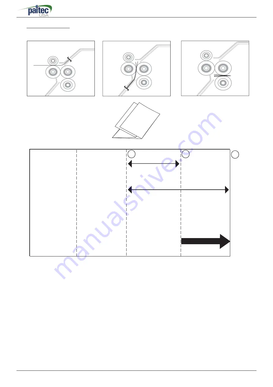
When setting a Double-Fold, please read the following steps.


1. Measure the length from line 1 to line 3 of the form as  indicated in the

               image above.  That measurement is the fold setting for the fi rst (upper 
               cassette) fold.


2. Measure the length from line 3 to line 2 of the form as indicated in the

               image above.  That measurement is the fold setting for the second   

               (lower cassette) fold.                  

A

Double Folding

Infeed Direction

First Fold (Upper Cassette)


Second Fold 

(Lower Cassette)

3

2

1

A

Summary of Contents for MX-6000

Page 1: ...User Manual MX 6000 User Manual Rev 070119 Model MX 6000...

Page 2: ...yright Any of the contents should not be copied re printed or translated by other languages without PAITEC USA approval Notice Caution Physical injury and serious mechanical damage will occur when dis...

Page 3: ...ying Parts 2 2 Caution for Installation Chapter 3 Preparing for Operation 3 1 Paper Size 3 2 Loading the Forms 3 3 Fold Setting 3 4 Fine Adjustment of Folding Position 3 5 Conveyor Wheel Setup Chapter...

Page 4: ...ollowing parts are included in the box Main body Inline interface unit and guide Power cable Power infeed fan power adaptor User s manual and fix bracket Jam removal handle and spare handle tips Spare...

Page 5: ...the label for electric information which is located at the back side of the machine When the power cable is properly connected please switch the machine on and check whether Ready sign is displayed o...

Page 6: ...sible to set up for users environment This function is needed when printing security documents 3 Initialize It makes the machine to be initialized to set up condition when first delivered from a wareh...

Page 7: ...Operating 2 1 Identifying Parts and Functions 3 1 6 2 5 4 1 Feeding Unit Safety Cover 2 Upper Fold Cassette Safety Cover 3 Large Capacity Tray 4 Lower Fold Cassette 5 Conveyor 6 Control Panel 7 Jam Re...

Page 8: ...y Level Sensor 1 2 5 6 2 1 3 1 Lower Cassette 2 Stopper 3 Stopper Adjustment Knob 4 Folding Scale Label 5 Stopper Locking Knob 3 2 1 1 Upper Cassette Handle 2 Folding Scale Label 3 Stopper Adjustment...

Page 9: ...yor Power Socket 7 Manual Feed Button 8 Fuse Socket 9 Lower Press Roller Cover 10 Upper Press Roller Cover 11 Jam Removal Holes Outfeed Unit 8 9 10 11 1 2 1 Conveyor Wheel 2 Conveyor 3 Conveyor Side G...

Page 10: ...9 MX 6000 User Manual 1 2 3 4 5 6 7 8 9 10 11 12 13 14 15 Name and Function of Each Button...

Page 11: ...stored after rebooting the machine 6 Thickness Sensor Button Thickness sensor function allows you to prevent any serious paper jams caused by double feeding or multiple sheet feeding Press the thickne...

Page 12: ...ng 9 Manual Feed Button Allows the processing of single damaged forms Press the manual feed button on the control panel Place the folded form at the entrance of the outfeed on the conveyor Then press...

Page 13: ...ize may result in paper jam or machine damage Important Please check whether any forms are stapled Staples will seriously damage the machine 3 2 Loading the Forms 1 Before loading the forms onto the m...

Page 14: ...all forms go to the upper cassette and then to the lower cassette Please refer to the images below to understand more about the path in which the forms are folded 2 Open the safety cover of the feedin...

Page 15: ...tment knob and turning the stopper locking knob clockwise 1 Unlock the fold position of the upper cassette by turning the stopper locking knob counter clockwise 2 Adjust the stopper so the red marker...

Page 16: ...tion carefully to fully understand the folding mechanism of MX 6000 1 The folding unit is composed of rollers cassettes and stoppers 2 The form enters in between the two front fold rollers 3 The form...

Page 17: ...anual 16 5 The folded form then exits the fold rollers and then are sent to the press unit 4 The form hits the lower cassette stopper and forms a buckle The folded form then enters in between the two...

Page 18: ...the length from line 1 to line 2 of the form as indicated in the image above That measurement is the fold setting for the first upper cassette fold 2 Measure the length from line 2 to line 3 of the f...

Page 19: ...se read the following steps 1 Measure the length from line 1 to line 2 of the form as indicated in the image above That measurement is the fold setting for the first upper cassette fold 2 Make sure th...

Page 20: ...3 of the form as indicated in the image above That measurement is the fold setting for the first upper cassette fold 2 Measure the length from line 3 to line 2 of the form as indicated in the image ab...

Page 21: ...ed in the image above That measurement is the fold setting for the first upper cassette fold 2 Measure the length from line 3 to line 2 of the form as indicated in the image above That measurement is...

Page 22: ...ne 4 of the form as indicated in the image above That measurement is the fold setting for the first upper cassette fold 2 Measure the length from line 4 to line 2 of the form as indicated in the image...

Page 23: ...folding is slightly off from the desired position please check the following possible causes a Incorrect fold setting b Machine clearance c Incorrect position of fold cassettes d The FRR or the fold r...

Page 24: ...r Left cover open Jam folder When a form does not reach the infeed sensor after infeed When a form is jammed at the infeed sensor When a form is jammed at the folding unit When a form is jammed at the...

Page 25: ...to remove the jam by using the jam free button 2 If the jam is not cleared by using the jam free button please use the jam removal handle to manually remove the jam When removing the jam turn the pres...

Page 26: ...ree different rollers 1 Pick up roller 2 Feed roller 3 Separate roller There is no certain life cycle for these rollers since it may vary depending on different environment forms and etc Read the foll...

Page 27: ...ontamination or toner residues on the surface of the fold rollers Caution Please do not use any other substance when cleaning the surface of the fold rollers as it may damage the rubber 3 Cleaning pre...

Page 28: ...is correct 6 3 Power On but No Start 1 Check if the left safety cover is opened 2 Check if the right safety cover is opened 3 Check if the lower cassette is pushed all the way in 4 Check for any pape...

Page 29: ...e main body of the conveyor like the picture Please loosen the screws and attach the side guide on both sides by using the same screws like the picture Please attach the lower bracket like the picture...

Page 30: ...29 MX 6000 User Manual Headquarters Factory 15951 SW 41st Street Suite 400 Davie FL 33331 E mail paitec paitec com Website www paitec com This page intentionally left blank...

Reviews: