background image


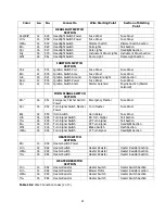
Color 

Ga.  No. 

Connect to 

Wire Starting Point 

Section of Starting 

Point 


WIPER SWITCH 

SECTION 


Blu  

18 

986  Wiper Switch 

Wiper Motor  

Wiper Motor Section 

LtBlu  

18 

987  Wiper Switch 

Wiper Motor  

Wiper Motor Section 

Blk  

18 

988  Wiper Switch 

Wiper Motor  

Wiper Motor Section 


WIPER MOTOR 

SECTION 


Ylw 

18 

989  Wiper Motor Power 

Fuse Panel 

Fuse Panel 

Blu 

18 

986  Wiper Motor 

Wiper Switch 

Wiper Switch Section 

LtBlu 

18 

987  Wiper Motor 

Wiper Switch 

Wiper Switch Section 

Blk 

18 

988  Wiper Motor 

Wiper Switch 

Wiper Switch Section 


INSTRUMENT PANEL 

SECTION 


Brn/Wht 

16 

970  Charge Light 

Fuse Panel 

Fuse Panel 

Brn/Wht 

16 

914  Charge Light 

Alternator 

Alternator Section 

LtGrn 

18 

936  High Beam Indicator 

Dimmer Switch 

Dimmer Switch Section 

LtBlu 

18 

937  Left Turn Indicator 

LF Turn Signal 

Turn Signal Switch Section 

Blu 

18 

938  Right Turn Indicator 

RF Turn Signal 

Turn Signal Switch Section 

Gry 

18 

930  Instrument Panel Lighting 

Headlight Switch 

Headlight Switch Section 

Tan 

16 

939  Fuel Gauge 

Fuel Sending Unit 

Tail Section 

Grn 

18 

921  Temp. Light 

Temp. Sending Unit 

Engine Section  

Blu 

18 

922  Oil Light 

Oil Pres. Sending Unit 

Engine Section  

Orn 

18 

981  Clock Power 

Fuse Panel 

Fuse Panel 

Blk/Wht 

14 

975  Ground 

Instrument Panel 

Instrument Panel Section 

Tan

1


18 

962  Brake Warning Light 

Pressure Switch & 

Emergency Brake 

Engine & Dash Sections 


RADIO SECTION 


Red 

16 

940  Radio Power Unswitched 

Fuse Panel 

Fuse Panel 

Ylw 

18 

941  Radio Power Switched 

Fuse Panel 

Fuse Panel 


DOME LIGHT SECTION   


Wht 

18 

961  Dome Light (Ground) 

Headlight Switch 

Headlight Switch Section 

Orn 

18 

945  Dome Light (Power) 

Fuse Panel 

Fuse Panel 


TAIL SECTION 


Grn 

16 

948  RR Turn Signal 

Turn Signal Switch 

Turn Signal Switch Section 

Ylw 

16 

949  LR Turn Signal 

Turn Signal Switch 

Turn Signal Switch Section 

Tan 

16 

939  Fuel Sending Unit 

Fuel Gauge 

Instrument Panel Section 

Brn 

16 

929  Tail Lights 

Headlight Switch 

Headlight Switch Section 

Lt.Grn 

16 

956  Backup Lights 

Backup Switch 

Dash Section 

 
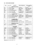
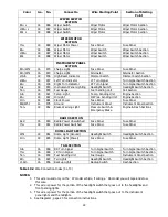
Table 10.2 Wire Connection Index (3 of 3) 

 
NOTES: 

1.


This wire is used only on the `67 model vehicle, if wiring a `66 model you will tape and stow  

 this wire. 

2.


This wire is power for the portion of the headlight switch that goes out to the headlights and  

       front parking lights. 
3.


This wire is power for the portion of the headlight switch that goes out to the instrument  

       panel lights and the taillights. 
4.


See Diagram1, page 23 for connection instructions. 


22 


Summary of Contents for 20110

Page 1: ...Wire Harness Installation Instructions For Installing 20110 Classic Customizable Chevy II Nova 1966 67 Harness 21 Circuit Manual 90522...

Page 2: ...structions please call or email us our contact information can be found at the top of this page or online at www painlessperformance com We sincerely appreciate your business Painless Performance Prod...

Page 3: ...kit is a sheet of pre printed labels to assist in identifying of connections as the existing harness is removed from the vehicle If you do not have an existing harness there is a package of terminals...

Page 4: ...4 7 0 General Harness Installation Instructions 4 7 1 Rough Installation 4 7 2 Terminal Installation and Making Connections 5 7 3 Grounding The Automobile 5 8 0 Harness Attachment by Section 6 8 1 Fu...

Page 5: ...gure 8 11 Wiper Motor and Engine Wire Routing 11 Figure 8 12 Wiper Motor Connections 11 Figure 8 13 Maxi Fuse 12 Figure 8 14 Electric Choke Connections 12 Figure 8 15 Alternator Connections 13 Figure...

Page 6: ...tem has been designed with three major groups incorporated into it TAIL DOME GROUP Includes taillights right and left turn signals brake light fuel tank sender and the dome light ENGINE GROUP Includes...

Page 7: ...wired in and fuses installed Tail Light Harness plugged into main harness Dome Light Harness plugged into main harness Fuseblock Mounting Plate Parts Kit contains terminals splices and extra fuses Hig...

Page 8: ...head connector at the firewall Disconnect the the other end of each of the wires and remove the harness from the vehicle 5 0 2 Locate the two screws that secure the fuse block to the firewall and rem...

Page 9: ...n the floor next to your vehicle and indentify all the SECTIONS You will want to route the harness through and around open areas Inside edges provide extra protection from hazards and also provides pl...

Page 10: ...cut the wire Remember to always allow enough slack in the harness and wires at places where movement could possibly occur such as automobile body to frame frame to engine ect Double check your calcula...

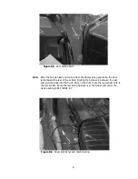
Page 11: ...e bolting the fuseblock to the adapter plate allowing the assembly to hang free 8 1 2 Route the DASH SECTION ignition instrument panel headlight switch etc around the kick panel over the steering colu...

Page 12: ...e Light Harness and route it from the door jamb switch on the drivers side along the bottom of the dash to the passenger side door jamb switch Connecting the white wires at the jamb switches and conne...

Page 13: ...e vehicle Routing the harness in between the rear seat and the body into the trunk Once in the truck route the fuel sender wire to the fuel sender Route the remaining harness over the fender and under...

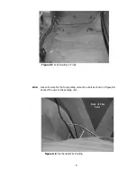
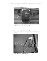
Page 14: ...Locate the wire for the fuel sending unit and route it as shown in Figure 8 8 Connect the wire to the sending unit 9 Figure 8 7 Wire Routing in Trunk Figure 8 8 Fuel Sender Wire Routing Back of Rear...

Page 15: ...light 8 2 6 Figure 8 10 shows the backup and brake tail light sockets You can remove the terminals from the sockets and solder the new wires to them or you can cut off the wire coming out of the socke...

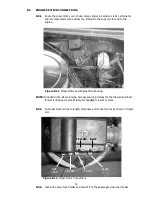
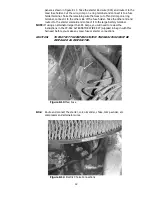
Page 16: ...6 large harness securing clamps for the firewall and inner fender routing and 2 small clamp for headlight crossover wires 8 3 2 Cut wiper motor wires to length terminate and connect wires as shown in...

Page 17: ...he starter solenoid and connect it to the large battery terminal NOTE If using an alternator larger than 65 Amps you will need to review the instructions in the PP 662 ALTERNATOR WIRE KIT supplied in...

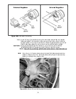
Page 18: ...r and terminals provided CAUTION If using an alternator larger than 65 amps you will need to use the PP 662 ALTERNATOR WIRE KIT supplied in a bag in the box with this harness Note This will be used al...

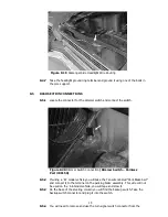
Page 19: ...t using one of the bolts in the core support 8 4 5 Route the passenger headlight and park turn wires across the front of the core support as shown Use the two small clamps supplied to secure the wires...

Page 20: ...ke Swt and connect it to the terminal on the parking brake assembly This wire will not be used on the 66 model vehicle you will tape and stow it 8 5 3 On the base of the steering column you will find...

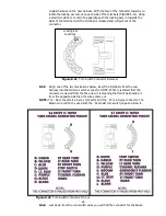
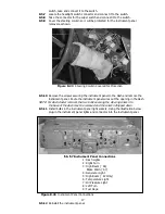
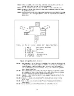
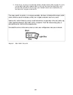
Page 21: ...ill pull out of the connector 8 5 5 Using one of the two illustrations below insert the terminals from the new harness into the old turn switch connector NOTE When it is stated that the connector is v...

Page 22: ...e dash and remove the instrument panel Route the instrument panel wires out the opening in the dash NOTE For dash cluster removal the two bolts securing the steering column to the base of the dash mus...

Page 23: ...ox through the light hole Cut this wire to the proper length and then strip the wire Take the glove box light and strip it also then splice the wires togather Once you have spliced the wire you can re...

Page 24: ...sed number such as the one at the end of this sentence Table 10 2 is divided into sections that correspond to the sections of your wire harness ENGINE SECTION DASH SECTION TAIL SECTION etc The Index i...

Page 25: ...OLENOID Red 10 916 Battery Positive or Starter Solenoid Large Terminal Fuse Panel Fuse Panel Ppl 12 919 Starter Solenoid S Term Ignition Switch Start Ignition Switch Section ALTERNATOR SECTION Brn Wht...

Page 26: ...gine Section Starter Solenoid TURN SIGNAL SWITCH SECTION Brn1 16 951 Emergency Flasher Switch Power Emergency Flasher Fuse Panel Ppl 16 952 Turn Signal Switch Flasher Power Turn Flasher Fuse Panel Blk...

Page 27: ...s Sending Unit Engine Section Orn 18 981 Clock Power Fuse Panel Fuse Panel Blk Wht 14 975 Ground Instrument Panel Instrument Panel Section Tan1 18 962 Brake Warning Light Pressure Switch Emergency Bra...

Page 28: ...t number RU11 The wiper switch connector is no longer available We have terminated the wiper switch wires with the correct terminals so that your original connector can be re used Remove the old termi...

Page 29: ...NOTES 24...
Page 30: ...original purchaser to be free from defects in material and workmanship under normal use Painless Performance will repair or replace defective products without charge during the first 12 months from t...

Reviews: