


IX
Table of Contents
TouchPad Failure . . . . . . . . . . . . . . . . . . . . . . . . . . . . . . . . . . . . . . . . . . . . . . .144
Internal Speaker Failure . . . . . . . . . . . . . . . . . . . . . . . . . . . . . . . . . . . . . . . . . .144
HDD Not Operating Correctly . . . . . . . . . . . . . . . . . . . . . . . . . . . . . . . . . . . . . .146
ODD Failure . . . . . . . . . . . . . . . . . . . . . . . . . . . . . . . . . . . . . . . . . . . . . . . . . . .147
Wireless Function Failure . . . . . . . . . . . . . . . . . . . . . . . . . . . . . . . . . . . . . . . . .150
Thermal Unit Failure . . . . . . . . . . . . . . . . . . . . . . . . . . . . . . . . . . . . . . . . . . . . .150
External Mouse Failure . . . . . . . . . . . . . . . . . . . . . . . . . . . . . . . . . . . . . . . . . . .151
Other Failures . . . . . . . . . . . . . . . . . . . . . . . . . . . . . . . . . . . . . . . . . . . . . . . . . .151
Intermittent Problems . . . . . . . . . . . . . . . . . . . . . . . . . . . . . . . . . . . . . . . . . . . . . . . .152
Undetermined Problems . . . . . . . . . . . . . . . . . . . . . . . . . . . . . . . . . . . . . . . . . . . . . .152
Post Codes . . . . . . . . . . . . . . . . . . . . . . . . . . . . . . . . . . . . . . . . . . . . . . . . . . . . . . . .153
Jumper and Connector Locations
159
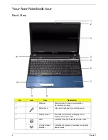
Top View . . . . . . . . . . . . . . . . . . . . . . . . . . . . . . . . . . . . . . . . . . . . . . . . . . . . . .159
Bottom View . . . . . . . . . . . . . . . . . . . . . . . . . . . . . . . . . . . . . . . . . . . . . . . . . . .160
USB/B Board . . . . . . . . . . . . . . . . . . . . . . . . . . . . . . . . . . . . . . . . . . . . . . . . . . .161
Power Board . . . . . . . . . . . . . . . . . . . . . . . . . . . . . . . . . . . . . . . . . . . . . . . . . . .161
3G/B Board . . . . . . . . . . . . . . . . . . . . . . . . . . . . . . . . . . . . . . . . . . . . . . . . . . . .162
CR/B Board . . . . . . . . . . . . . . . . . . . . . . . . . . . . . . . . . . . . . . . . . . . . . . . . . . . .162
Clearing Password Check and BIOS Recovery . . . . . . . . . . . . . . . . . . . . . . . . . . . .163
Clearing Password Check . . . . . . . . . . . . . . . . . . . . . . . . . . . . . . . . . . . . . . . . .163
Clear CMOS Jumper . . . . . . . . . . . . . . . . . . . . . . . . . . . . . . . . . . . . . . . . . . . . .163
BIOS Recovery by Crisis Disk . . . . . . . . . . . . . . . . . . . . . . . . . . . . . . . . . . . . .164
FRU (Field Replaceable Unit) List
165
EasyNote Exploded Diagrams . . . . . . . . . . . . . . . . . . . . . . . . . . . . . . . . . . . . . . . . .166
Main Assembly . . . . . . . . . . . . . . . . . . . . . . . . . . . . . . . . . . . . . . . . . . . . . . . . .166
Upper Assembly . . . . . . . . . . . . . . . . . . . . . . . . . . . . . . . . . . . . . . . . . . . . . . . .167
LCD Assembly . . . . . . . . . . . . . . . . . . . . . . . . . . . . . . . . . . . . . . . . . . . . . . . . .168
FRU List . . . . . . . . . . . . . . . . . . . . . . . . . . . . . . . . . . . . . . . . . . . . . . . . . . . . . . . . . .169
Screw List . . . . . . . . . . . . . . . . . . . . . . . . . . . . . . . . . . . . . . . . . . . . . . . . . . . . . . . . .176
Model Definition and Configuration
178
Packard Bell EasyNote TM86 . . . . . . . . . . . . . . . . . . . . . . . . . . . . . . . . . . . . . . . . . .179
Packard Bell EasyNote TM87 . . . . . . . . . . . . . . . . . . . . . . . . . . . . . . . . . . . . . . . . . .182
Packard Bell EasyNote TM89 . . . . . . . . . . . . . . . . . . . . . . . . . . . . . . . . . . . . . . . . . .185
Test Compatible Components
187
Microsoft® Windows® 7 Environment Test . . . . . . . . . . . . . . . . . . . . . . . . . . . . . . .188
Online Support Information
201
Index 203
Summary of Contents for TM86 Series
Page 6: ...VI ...
Page 10: ...X Table of Contents ...
Page 15: ...Chapter 1 5 System Block Diagram ...
Page 62: ...52 Chapter 3 4 Remove one 1 screw from the 3G module 5 Lift the 3G card from the slot ...
Page 73: ...Chapter 3 63 3 Disconnect the following four 4 cables from the Mainboard A B C D ...
Page 78: ...68 Chapter 3 5 Lift the Right Speaker Module clear of the upper cover ...
Page 83: ...Chapter 3 73 5 Lift the card reader board clear of the device ...
Page 85: ...Chapter 3 75 5 Lift the USB board clear of the device ...
Page 92: ...82 Chapter 3 5 Carefully lift the Thermal Module clear of the Mainboard ...
Page 101: ...Chapter 3 91 5 Turn the board over and disconnect the cable ...
Page 103: ...Chapter 3 93 4 Lift the LCD Panel clear of the module ...
Page 105: ...Chapter 3 95 5 Disconnect the LVDS cable from the panel ...
Page 107: ...Chapter 3 97 5 Lift the microphone set clear of the panel ...
Page 114: ...104 Chapter 3 4 Replace six 6 securing screws three on each side of the LCD Panel brackets ...
Page 126: ...116 Chapter 3 6 Connect the LVDS cable and lock the connector 7 Connect the microphone cable ...
Page 131: ...Chapter 3 121 4 Replace the FFC and press down as indicated to secure it to the Upper Cover ...
Page 187: ...Chapter 6 177 ...
Page 188: ...Appendix A 178 Model Definition and Configuration Appendix A ...
Page 212: ...202 Appendix C ...
Page 216: ...206 ...