


Appendix B
199
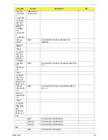
Thermal Module (UMA)
CCI
Delta
NEW70_UMA_THM_MAIN_ASSY_Delta_CCI
CCI
ADDA
NEW70_UMA_THM_MAIN_ASSY_ADDA_CCI
Robin
Delta
NEW70_UMA_THM_MAIN_ASSY_Delta_ROBI
N
Robin
ADDA
NEW70_UMA_THM_MAIN_ASSY_ADDA_ROB
IN
AVC
Delta
NEW70_UMA_THM_MAIN_ASSY_Delta_AVC
AVC
ADDA
NEW70_UMA_THM_MAIN_ASSY_ADDA_AVC
Sunon
Sunon
NEW70_UMA_THM_MAIN_ASSY_SUNON_SU
NON
CCI
Delta
NEW70_PARK_THM_MAIN_ASSY_Delta_CCI
CCI
ADDA
NEW70_PARK_THM_MAIN_ASSY_ADDA_CCI
Robin
Delta
NEW70_PARK_THM_MAIN_ASSY_Delta_ROB
IN
Robin
ADDA
NEW70_PARK_THM_MAIN_ASSY_ADDA_RO
BIN
AVC
Delta
NEW70_PARK_THM_MAIN_ASSY_Delta_AVC
AVC
ADDA
NEW70_PARK_THM_MAIN_ASSY_ADDA_AV
C
Sunon
Sunon
NEW70_PARK_THM_MAIN_ASSY_SUNON_S
UNON
CCI
Delta
NEW70_MADISON_THM_MAIN_ASSY_Delta_
CCI
CCI
ADDA
NEW70_MADISON_THM_MAIN_ASSY_ADDA
_CCI
Robin
Delta
NEW70_MADISON_THM_MAIN_ASSY_Delta_
ROBIN
Robin
ADDA
NEW70_MADISON_THM_MAIN_ASSY_ADDA
_ROBIN
AVC
Delta
NEW70_MADISON_THM_MAIN_ASSY_Delta_
AVC
AVC
ADDA
NEW70_MADISON_THM_MAIN_ASSY_ADDA
_AVC
Sunon
Sunon
NEW70_MADISON_THM_MAIN_ASSY_SUNO
N_SUNON
Core Logic
CLK GEN
SILEGO
S IC SLG8SP626VTR QFN 72P CLK GEN
GbE LAN
BROADCOM
S IC BCM57780A1KMLG QFN 48P E-LAN
CTRL
EC
ENE
S IC KB926QFD3 LQFP 128P KB CONTROL
Card
Reader
Controller
ENE
S IC UB6250NF A1-110 QFN 32P CARD
READER
BIOS
MXIC
S IC FL 16M MX25L1605DM2I-12G SOP 8P
ROM
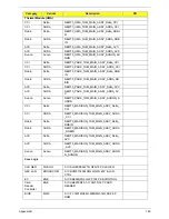
Category
Vendor
Description
PN
Summary of Contents for TM86 Series
Page 6: ...VI ...
Page 10: ...X Table of Contents ...
Page 15: ...Chapter 1 5 System Block Diagram ...
Page 62: ...52 Chapter 3 4 Remove one 1 screw from the 3G module 5 Lift the 3G card from the slot ...
Page 73: ...Chapter 3 63 3 Disconnect the following four 4 cables from the Mainboard A B C D ...
Page 78: ...68 Chapter 3 5 Lift the Right Speaker Module clear of the upper cover ...
Page 83: ...Chapter 3 73 5 Lift the card reader board clear of the device ...
Page 85: ...Chapter 3 75 5 Lift the USB board clear of the device ...
Page 92: ...82 Chapter 3 5 Carefully lift the Thermal Module clear of the Mainboard ...
Page 101: ...Chapter 3 91 5 Turn the board over and disconnect the cable ...
Page 103: ...Chapter 3 93 4 Lift the LCD Panel clear of the module ...
Page 105: ...Chapter 3 95 5 Disconnect the LVDS cable from the panel ...
Page 107: ...Chapter 3 97 5 Lift the microphone set clear of the panel ...
Page 114: ...104 Chapter 3 4 Replace six 6 securing screws three on each side of the LCD Panel brackets ...
Page 126: ...116 Chapter 3 6 Connect the LVDS cable and lock the connector 7 Connect the microphone cable ...
Page 131: ...Chapter 3 121 4 Replace the FFC and press down as indicated to secure it to the Upper Cover ...
Page 187: ...Chapter 6 177 ...
Page 188: ...Appendix A 178 Model Definition and Configuration Appendix A ...
Page 212: ...202 Appendix C ...
Page 216: ...206 ...