background image

1313131313

Packard Bell EasyNote MX Disassembly Manual

13

Bluetooth (Optional)

To remove the optional Bluetooth module, first remove the battery (see

Battery

), the HDD (see

Hard Disk

Drive

), the CD-ROM or DVD drive (see

Optical Disk Drive

), the wireless network card (see

WLAN Card

),

the installed memory (see

Memory

), the CPU (see

Processor

), the keyboard (see

Keyboard

), remove the

LCD screen (see

LCD Screen Assembly

), the main board

up to step 8

 (see

Main Board

), and then

perform the following steps:

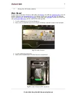
1.  Carefully disconnect the Bluetooth cable.

Fig. 21 Location of Bluetooth module and connector.

2.  Extract the Bluetooth module; the module has been clicked into place (see

Fig. 21

).

Touchpad

To remove the touchpad, first remove the battery (see

Battery

), the HDD (see

Hard Disk Drive

), the CD-

ROM or DVD drive (see

Optical Disk Drive

), the wireless network card (see

WLAN Card

), the installed

memory (see

Memory

), the CPU (see

Processor

), the keyboard (see

Keyboard

), remove the LCD screen

(see

LCD Screen Assembly

), the main board top cover

up to step 7

 (see

Main Board

), and then perform

the following steps:

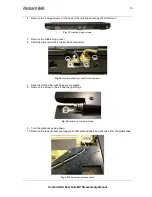
1.  Remove the 2 screws securing the touchpad buttons board to the top cover.

Fig. 22 Location of touchpad buttons board.

Summary of Contents for MX

Page 1: ...Packard Bell EasyNote MX Disassembly Manual...

Page 2: ...e 3 Avoid Electrostatic Discharge 3 Power Supply Unit 3 Battery 4 Hard Disk Drive 4 Optical Disk Drive 5 WLAN Card 5 Memory 6 Processor 7 Keyboard 8 LCD Screen Assembly 9 Main Board 11 Modem 12 Blueto...

Page 3: ...create a safety hazard Any indication of component replacement or printed wiring board modifications may void any warranty or exchange allowances Disassembly When disassembling the system unit follow...

Page 4: ...til it is un installed in the notebook Power Supply Unit Under no circumstances should you attempt to disassemble the power supply The power supply contains no user serviceable parts Inside the power...

Page 5: ...ocks in the direction of the arrows to the release the battery compartment cover and remove the cover 4 Take the battery out of the compartment Fig 1 Removing battery Hard Disk Drive To remove the HDD...

Page 6: ...HDD cover see Hard Disk Drive and then perform the following steps 1 Locate and remove the screw securing the optical disk drive in the hard disk drive compartment Fig 4 Location of optical disk drive...

Page 7: ...AN antenna cable connectors 3 Release the 2 metal clips securing the WLAN card Fig 6 Releasing metal clips 4 Take out the WLAN card from the slot Memory To remove the memory installed first remove the...

Page 8: ...ule s Fig 7 Removing memory module Processor To remove the CPU first remove the battery see Battery and then perform the following steps 1 Remove the 7 screws retaining the CPU cover see Fig 1 2 Remov...

Page 9: ...eat sink 6 Turn the screw in the CPU socket 180 degrees to release the CPU 7 Take out the CPU Keyboard To remove the keyboard first remove the battery see Battery and then perform the following steps...

Page 10: ...oard gently forward 6 Before removing the keyboard entirely carefully disconnect the keyboard flat cable from the main board LCD Screen Assembly To remove the LCD screen assembly remove the battery se...

Page 11: ...r 6 Carefully disconnect the 2 white block connectors Fig 14 Location of block connectors and screws 7 Slide the left and the right hinge cover outward 8 Remove the screw in the left and the right hin...

Page 12: ...Card the installed memory see Memory the CPU see Processor the keyboard see Keyboard remove the LCD screen see LCD Screen Assembly and then perform the following steps 1 Turn the notebook over so the...

Page 13: ...the optional Bluetooth cable from the main board see Fig 21 10 Remove the 3 screws securing the main board see Fig 19 11 Extract the main board from the casing 12 Optionally you might need to remove...

Page 14: ...lly disconnect the Bluetooth cable Fig 21 Location of Bluetooth module and connector 2 Extract the Bluetooth module the module has been clicked into place see Fig 21 Touchpad To remove the touchpad fi...

Page 15: ...emove the LCD screen see LCD Screen Assembly the main board top cover up to step 7 see Main Board and then perform the following steps 1 Disconnect the speaker cable from the main board see Fig 19 2 R...

Page 16: ...rive see Optical Disk Drive the wireless network card see WLAN Card the installed memory see Memory the CPU see Processor the keyboard see Keyboard remove the LCD screen see LCD Screen Assembly and th...

Page 17: ...eyboard remove the LCD screen see LCD Screen Assembly disassemble the LCD panel up to step 3 see LCD Panel and then do the following 1 Disconnect all cables from the inverter board see Fig 27 2 Remove...

Page 18: ...D Panel and then do the following 1 Disconnect the cable from the webcam see Fig 29 2 Remove the USB cable the microphone cable is attached to the same cable WLAN Antenna To remove the wireless antenn...

Page 19: ...DAMAGES RESULTING FROM THE FURNISHING PERFORMANCE OR USE OF THIS MATERIAL Copyright 2006 Packard Bell B V All rights reserved Packard Bell is a trademark of Packard Bell B V The names of actual compan...

Reviews: