17
6. Turn over the system board: the PCMCIA slot is now facing away
from you.
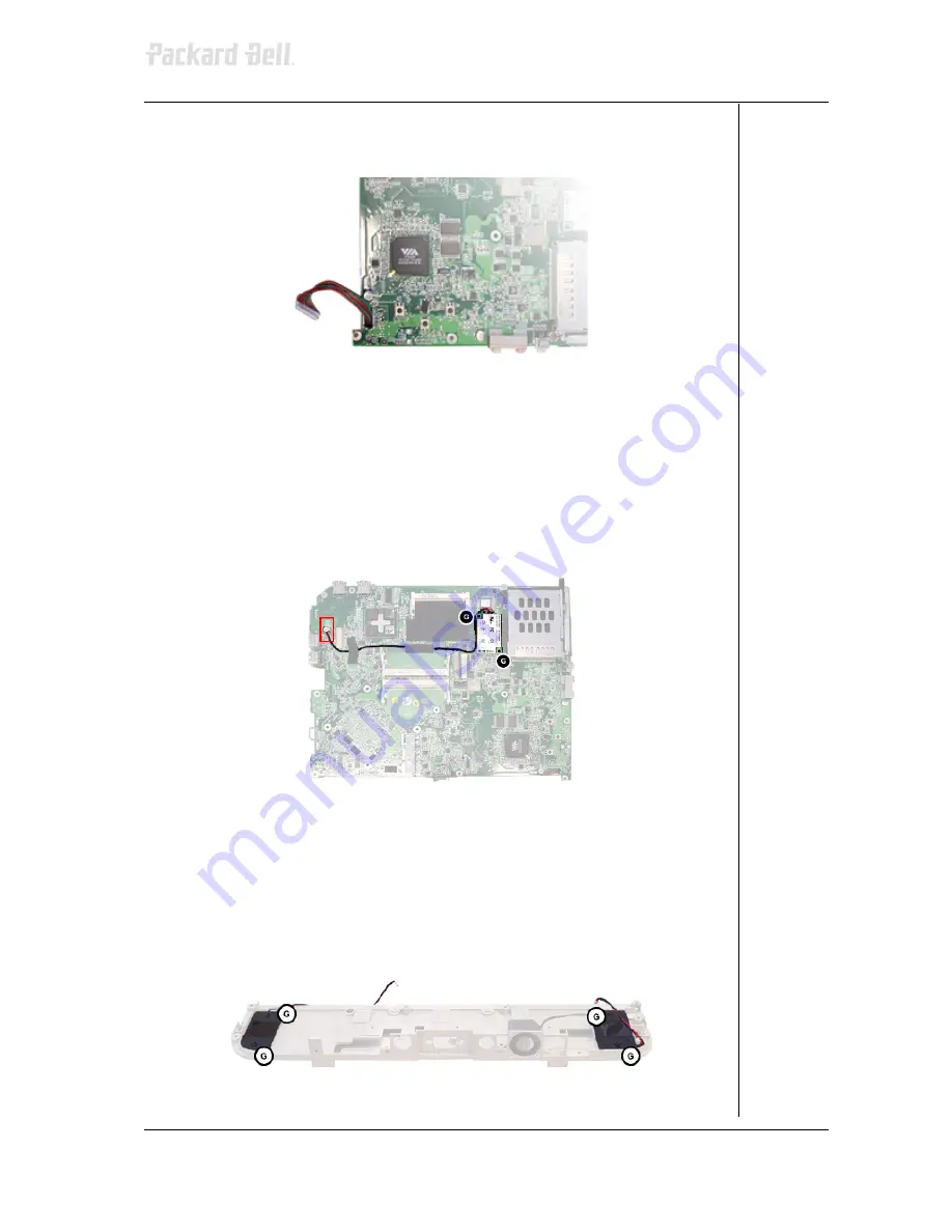
7. Remove the LED board assembly cable from the system board.
Fig. 33:
Disconnecting the LED board assembly cable.
Modem
1. Disconnect the modem cable from the connector on the system
board.
2. Remove the tape securing the modem cable to the system board.
3. Remove the 2 screws (G) securing the modem to the system board.
4. Remove the modem from the system board.
5. Remove the modem cable from the modem.
Fig. 34:
Removing the modem
Speakers
1. Remove the 2 screws (G) from the left speaker (with the short cable).
2. Remove the speaker cover from the left speaker.
3. Turn over the I/O plate and remove the 2 screws (G) and remove the
speaker.
4. Perform the same steps for the right speaker (with the long cable).
Fig. 35:
Removing the speakers
Packard Bell Easynote M3 Disassembly Manual


