background image

EasyNote K5


10. MainBoard


a.  Loosen five screws on top cover. 


Fig. 19: Top Cover 


b.  Unscrews seventeen screws on the bottom cover. 


Fig. 20: Bottom Cover 


Summary of Contents for EasyNote K5

Page 1: ...EasyNote K5 EasyNote K5 Disassembly Manual Version 1 1 Required Tools Disassembly Instructions DIP Switch Setting Reassembly Instructions ...

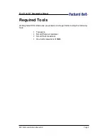
Page 2: ...EasyNote K5 Required Tools All EasyNote K5 maintenance procedures can be performed using the following tools Tweezers Small Philips screwdriver Small Flat screwdriver Hex bolt screwdriver Ø 5MM ...

Page 3: ...re removed are shown next to the image of the parts themselves When disassembling the system unit follow these general rules Do not disassemble the system into parts that are smaller than those specified in the instructions Label all removed connectors Note where the connector goes and in what position it was installed Turn off the power and disconnect all power and all options Also remove any PC ...

Page 4: ...EasyNote K5 1 Battery Remove the battery pack of the notebook as follows a Unlock the battery b Pull outward and lift up the battery Fig 1 Remove Battery ...

Page 5: ...le at the bottom of unit b Carefully slide the hard disk module out from base unit Fig 2 Hard Disk Module c Unscrew six screws at the side of the hard disk module Fig 3 Hard Disk Module d Carefully separate hard disk drive from hard disk shield and hard disk connector A B A A A A B B ...

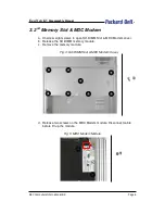
Page 6: ...ht screws to open SO DIMM Slot MDC Modem cover b Release the SO DIMM memory module c Remove the memory module Fig 4 SO DIMM Slot MDC Modem Cover d Release two screws on the MDC Modem module Disconnect cable before lift up the module Fig 5 MDC Modem Module ...

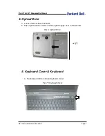
Page 7: ... Drive a Loosen three screws at bottom b Push optical drive out form unit through the gaps near to third screw Fig 6 Optical Drive 5 Keyboard Cover Keyboard a Push toward left to release Keyboard Cover Fig 7 Keyboard Cover ...

Page 8: ...EasyNote K5 b Unscrew three screws that secure the keyboard Fig 8 Keyboard c Disconnect keyboard connector Fig 8 Keyboard Connector ...

Page 9: ...t RAM Slot a Open up the black plastic cover and remove RAM from 1st RAM slot Fig 9 1st RAM Slot 7 CPU b Unscrew five screws on the CPU Fan module disconnect fan connect before remove it from base Fig 10 CPU Fan Module ...

Page 10: ...EasyNote K5 c Unscrew three heat sink screws and disconnect the fan connection Fig 11 Heat sink assembly d Carefully lift up heat sink assembly Fig 12 Heat sink assembly ...

Page 11: ...EasyNote K5 e Unlock the CPU from CPU socket and lift up CPU with care Fig 13 CPU socket ...

Page 12: ...EasyNote K5 8 LCD Module a Disconnect LCD connector at both sides Fig 14 LCD cable b Loosen four screws from the hinges before lifting up the LCD panel Fig 15 LCD module ...

Page 13: ...EasyNote K5 9 LCD Panel Disassembly a Remove four screws on LCD bezel Fig 16 LCD module b Push at edge of LCD bezel toward inside and carefully separate it from LCD base Fig 17 LCD Bezel ...

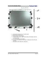
Page 14: ...rd e Take away the inverter board f Unscrew eight screws A B that hold the LCD brackets onto the LCD base cover g Lift out the LCD panel assembly h Unscrew four screws A at the side of LCD panel to free the LCD brackets i Disconnect LCD cable from LCD panel A A C A A A A A A A A A B B B B C A C B ...

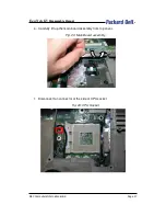
Page 15: ...EasyNote K5 10 MainBoard a Loosen five screws on top cover Fig 19 Top Cover b Unscrews seventeen screws on the bottom cover Fig 20 Bottom Cover A B A A B A A A A A A A A A A A A C C ...

Page 16: ...EasyNote K5 c Loosen four hexbolts and one screw at the rear of the base unit Fig 21 Rear Cover d Carefully lift up the bottom cover Fig 22 Bottom Cover A A A A B A B ...

Page 17: ...EasyNote K5 e Carefully lift up the main board assembly from top cover Fig 23 Main Board assembly f Disconnect fan connector at the side of CPU socket Fig 24 CPU Socket ...

Page 18: ...EasyNote K5 g Remove four screws and disconnect fan connection on main board Fig 25 Main Board assembly h Carefully separate the main board from heat plate Fig 26 Main Board ...

Page 19: ...screws on the audio board and disconnect five connectors before separate it from top cover Fig 27 Audio Board 12 Speaker a Loosen four screws at both side of speaker before you can remove it from front cover Fig 28 Speaker A A B A A A B B A B ...

Page 20: ...Note K5 13 Touch Pad a Unscrew one screw on the touch pad before remove it from top cover Fig 29 Touch Pad 14 LED Board a Remove three screws on LED Board before separate it from top cover Fig 31 LED Board ...

Page 21: ...tructions Reassembly is the reverse of the disassembly process Use care to ensure that all cables and screws are returned to their proper positions DIP Switch Settings No DIP switches available on the EasyNote K5 Kigem mainboard ...

Reviews: