background image

Page 11

For technical questions, please call 1-800-444-3353.

SKU 65351 


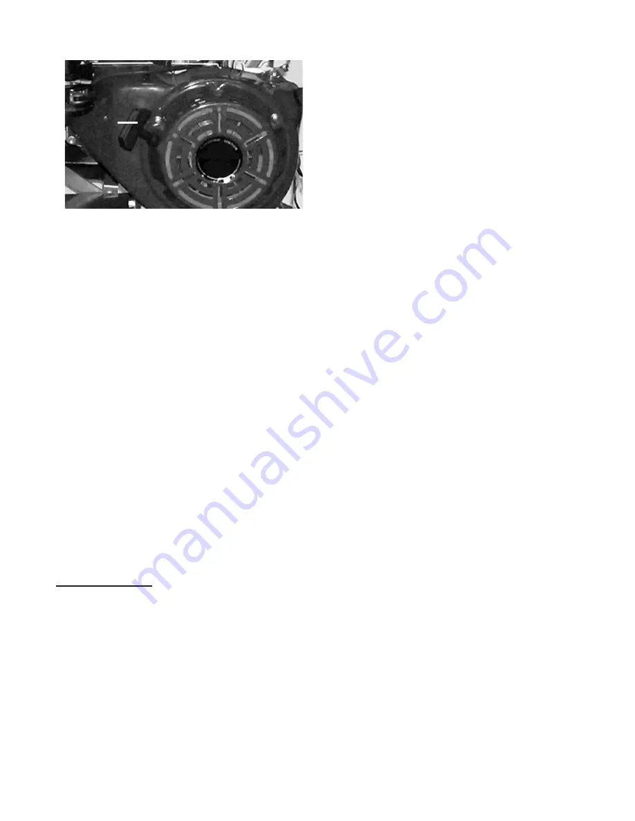
FIGURE H

STARTER

HAndLE

(16K)

3.  Grasp the Starter Handle (16K), and 

pull slowly until resistance is felt.  While 

holding the Handle, allow the Starter 

Rope to rewind slowly.  Then, pull the 

Starter Handle with a rapid, full arm 

stroke.  Once again while holding the 

Handle, allow the Rope to rewind slowly.  

Repeat as necessary, until the Engine 

starts. 

(See Figure H.)

After the Engine starts and warms up, 

4. 

slowly move the Choke Lever (22G) to 

its “RUN” position.  

(See Figure F.)

To adjust the Engine’s speed, move 

5. 

the Engine Throttle (23G) to the left for 

increased speed.  Move the Throttle to 

the right for decreased speed. 

(See Figure F.)

IMPORTANT:  Allow the Engine to run 

6. 

at no load until warm (1-5 minutes) and 

with no load after each start-up to allow 

the Engine to stabilize.

Break-in Period:

Breaking-in the Engine will help to 

a. 

ensure proper equipment and operation, 

and will extend the Engine’s lifespan.  

The warranty is void if the Engine is not 

broken in properly.  The first 20 hours of 

operation is the break-in period.

During the first 3 hours of use:

b. 

Do not apply a heavy load to 

• 

equipment.
Do not operate the Engine at its 

• 

maximum speed.

After the first 20 hours of use:

c. 

Change the engine oil.

• 

Under normal operating conditions 

subsequent maintenance follows the 

schedule explained in MAINTENANCE 

AND SERVICING section.
Once Engine starts, the Water Pump will 

7. 

run continuously until Engine is turned 

off.  To turn off the Engine, turn the 

Power Switch (6K) off.  

(See Figure G.)

IMPORTANT: 

8. 


If the machine’s Impeller 

strikes a foreign object, or if the machine 

begins making an unusual noise or 

vibrates excessively, immediately shut 

off the Engine.  Allow the Impeller to 

come to a complete stop.  Remove the 

Spark Plug (10D) from the Engine.  Then 

perform the following steps:

Clear the obstruction.

a. 

Inspect for damage.

b. 

Repair or replace damaged parts.

c. 

Check for any loose parts and tighten to 

d. 

ensure continued safe operation.

Do not leave the Water Pump 

9. 

unattended when it is running.  Turn off 

the Engine before leaving the work area.

When finished, turn the Engine’s Power 

10. 

Switch (6K) off.  Wait until the Water 

Pump completely stops.  Allow the 

Engine to completely cool before moving 

or storing the Water Pump.

Summary of Contents for 65351

Page 1: ...ut the express written consent of Harbor Freight Tools Diagrams within this manual may not be drawn proportionally Due to continuing improvements actual product may differ slightly from the product de...

Page 2: ...ntal Protection Agency and by the California Air Resources Board also known as CARB For warranty information refer to the last two pages of this manual NOTE At high altitudes the engine s carburetor g...

Page 3: ...result in fire serious injury and or DEATH The warnings and precautions discussed in this manual cannot cover all possible conditions and situations that may occur It must be understood by the operato...

Page 4: ...other piece of equipment Do not operate in explosive 7 atmospheres such as in the presence of flammable liquids gases or dust Gasoline powered engines may ignite the dust or fumes Stay alert watch wha...

Page 5: ...ment for a purpose for which it is not intended Industrial applications must follow OSHA 22 guidelines Service precautions Before service maintenance or 1 cleaning Turn the Power Switch 6K to its a OF...

Page 6: ...a well ventilated area only d Save these instructions UNPACKING When unpacking check to make sure all of the parts shown on the Parts List in this manual are included If any parts are missing or broke...

Page 7: ...ach Hose to Intake Filter 37 Use a screwdriver to tighten Hose Clamp until secure See Figure 5 For the Discharge Hose not included 5 slide the other Hose Coupler 35 over the other Hose Coupling 34 Ins...

Page 8: ...the Pump during the initial operation Route the Intake Hose with the Intake 3 Filter fully immersed in the water supply source Place Filter into water to be pumped 4 WARNING Filter must be fully imme...

Page 9: ...afety Information section at the beginning of this manual including all text under subheadings therein before set up or use of this product Starting the Engine Inspect Engine and Water Pump for damage...

Page 10: ...neck of the Tank with unleaded gasoline Then replace the Fuel Filler Cap 9H 6 Start Procedure Before starting the Engine Follow the Assembly Instructions to a prepare the equipment Inspect the equipm...

Page 11: ...hours of operation is the break in period During the first 3 hours of use b Do not apply a heavy load to equipment Do not operate the Engine at its maximum speed After the first 20 hours of use c Cha...

Page 12: ...cluded 1 underneath the crankcase s Drain Plug 1B See Figure A Remove the Drain Plug 1B and if 2 possible tilt the Crankcase 5B slightly to help drain the oil out Recycle used oil See Figure A Replace...

Page 13: ...Every 50 Operation Hours Change engine oil a Every 100 Operation Hours Replace Spark Plug a Replace Air Filter Element b Note All maintenance procedures scheduled for 25 50 and 100 operation hours sh...

Page 14: ...Note If the Water Pump is not in use due to dry conditions etc prime Front Case and activate the unit once every month In Cold Weather When the Water Pump is not in use a protect the interior of the...

Page 15: ...plug wire or spark plug broken 4 Incorrect spark timing or faulty ignition 5 system Ignition spark Related Connect spark plug wire properly 1 Clean spark plug 2 Correct spark plug gap 3 Replace spark...

Page 16: ...r high 4 altitude operation Intake valve stuck choke stuck 5 incorrect timing clogged carburetor or overheated engine Fill fuel tank with fresh 87 octane unleaded 1 gasoline Use cold weather fuel and...

Page 17: ...2 1 17 Wide Washer 1 30 Key 4 x 35 1 5 Washer 1 18 Primary Impeller 1 31 Front Case 1 6 Non Return Flap 1 19 Fluted Flange 1 32 Manifold Gasket 1 7 Non Return Weight 1 20 Secondary Impeller 1 33 Disch...

Page 18: ...d not by the buyer The buyer assumes all risk and liability arising out of his or her repairs to the original product or replacement parts thereto or arising out of his or her installation of replacem...

Page 19: ...shaft Oil Seal 1 14B Fly Weight Pin 2 5B Crankcase 1 15B Governor Driven Gear 1 6B Sway Bar 1 16B Governor Fly Weight 2 7B Washer 1 17B Governor Driven Gear Sub Assy 1 8B Keeper 1 18B Snap Ring 1 9B N...

Page 20: ...part number with the suffix C Example Oil Plug Sub Assembly Part 1C Part Description Qty Part Description Qty 1C Oil Plug Sub Assy 1 7C Set Pin 2 2C Oil Plug 1 8C Dipstick 1 3C Oil Plug Seal 2 9C Dip...

Page 21: ...ption Qty 1D Bolt M6 x 12 6 10D Spark Plug 1 2D Air Duct 1 11D Exhaust Valve Guide 1 3D Intake Valve Guide 1 12D Circlip 1 4D Lower Flow Guard 1 13D Cylinder Head Bolt 4 5D Stud M6 x 113 2 14D Cylinde...

Page 22: ...Part Description Qty Part Description Qty 1E Piston Ring I 1 10E Connecting Rod Shank 1 2E Piston Ring II 1 11E Connecting Rod Cap 1 3E Side Rail 2 12E Bolt 2 4E Expander 1 13E Connecting Rod 1 5E 3 P...

Page 23: ...cription Qty Part Description Qty 1F Lock Nut 2 9F Flyweight Spring 1 2F Rocker Shaft Seat 2 10F Camshaft Assy 1 3F Valve Rocker 2 11F Exhaust Valve 1 4F Valve Gap Adjusting Bolt 2 12F Intake Valve 1...

Page 24: ...lerating Lever 1 4G Idle Adjusting Screw 1 19G Accellerating Lever Washer 1 5G Mixture Chamber Body 1 20G Bolt M4 2 6G Main Nozzle 1 21G Cover 1 7G Main Jet 1 22G Choke Lever 1 8G Float 1 23G Throttle...

Page 25: ...d part number with the suffix H Example Pipe Clamp Part 1H Part Description Qty Part Description Qty 1H Pipe Clamp 2 7H Filter Cup 1 2H Outlet Pipe 1 8H Packing Ring 1 3H Bolt M6 x 22 1 9H Fuel Filler...

Page 26: ...ate the part name and part number with the suffix I Example Air Cleaner Cover Part 1I Part Description Qty Part Description Qty 1I Wing Nut 2 7I Screw M5x12 2 2I Air Cleaner Cover 1 8I Air Cleaner Bas...

Page 27: ...NT NOTE When ordering engine parts indicate the part name and part number with the suffix J Example Nut M8 Part 1J Part Description Qty Part Description Qty 1J Screw M5x8 4 5J Exhaust Muffler 1 2J Muf...

Page 28: ...iption Qty 1K Bolt M6 x 22 1 11K Friction Spring 1 2K Crankcase Side Plate Assy 1 12K Spring Lid 1 3K Bolt M6 x 18 3 13K Set Screw 1 4K Fan Hood Assy 1 14K Starter Roll 1 5K Bolt M6 x 12 5 15K Rope 1...

Page 29: ...L Example Nut M6 Part 1L Part Description Qty Part Description Qty 1L Nut M6 1 9L Extension Spring 1 2L Positioning Plate 1 10L Back Spring 1 3L Spring Washer 1 11L Governor Assistant Spring 1 4L Hand...

Page 30: ...s List and Assembly Diagram M IMPORTANT NOTE When ordering engine parts indicate the part name and part number with the suffix M Example Nut M14 x 1 5 Part 1M Part Description Qty Part Description Qty...

Page 31: ...ly Diagram N IMPORTANT NOTE When ordering engine parts indicate the part name and part number with the suffix N Example Bolt M6 x 25 Part 1N Part Description Qty Part Description Qty 1N Bolt M6 x 25 2...

Page 32: ...vary from state to state 3491 Mission Oaks Blvd PO Box 6009 Camarillo CA 93011 800 444 3353 Emission Control System Warranty California and United States Emission Control Defects Warranty Statement T...

Page 33: ...also be excluded for any part which fails malfunctions or is damaged due to failure to follow the maintenance and operating instructions set forth in the Owner s Manual including but not limited to U...

Reviews: