SINC 250314-24 9
Into a Factory Built Fireplace
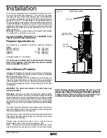
Your Insert may be installed into a factory built fi replace (size
permitting) with the following requirements:
1) Inspect your fi replace for damage or other physical de-
fects. The fi replace must be in good working condition.
If in doubt about its condition, seek professional advice.
Check for creosote build up or other obstructions inside
the chimney, especially if it has not been in use for some
time. Before installing, clean your chimney system thor-
oughly.
2) A full stainless steel rigid or fl exible fl ue liner meeting
type HT requirements (2100°F) per UL1777 (U.S.) or
ULC S635 (Canada) must be used for both safety and
performance. The liner must be securely attached to the
Insert fl ue collar and the chimney top.
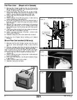
3) The surround must be sealed to the fi replace front or the
damper area around the chimney liner must be sealed
to prevent room air entering the chimney cavity of the
fi replace.
4) The air fl ow within and around the fi replace must not be
altered by the installation of the Insert (i.e. no blockage of
louvers or cooling air inlet or outlet ports). This includes
the circulating air chambers in a steel fi replace or metal
heat circulator.
5) Alteration of the fi replace in any manner is not permitted
with the following exceptions:
a: external trim pieces which do not affect the operation
of the fi replace may be removed and stored on or within
the fi replace for re-assembly if the Insert is removed.
b: the chimney damper may be removed to install the
liner.
Combustion Air
Consult local building codes regarding combustion air sup-
ply. Intake or combustion air can be supplied to the Insert in
one of two ways:
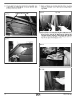
1) Outside air supply: Remove cover from ash clean out in
existing fi replace. Place a rodent screen in place of the
cover. Install the Insert as described in the "Installation"
section, making sure not to cover the opening of the air
inlet. When installation is complete, seal surround to fi re-
place and anywhere else air may enter. This will ensure
combustion air is drawn from outside the house and into
the 9" x 2" intake at the lower rear of the appliance.
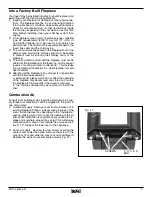
2) Room air supply: Remove the two screws securing the
center cover under the ashlip. Remove the screw in the
cover box front and slide the cover box out and discard.
Replace the center cover and tighten screws. Fig. #7).
Fig. # 7
SCREWS
C O V E R
BOX
Summary of Contents for SUMMIT INSERT
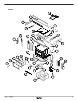
Page 21: ...SINC 250314 24 21 Fig 25...
Page 22: ...22 SINC 250314 24 NOTES...


