background image

©2001 PACE Inc., Laurel, Maryland

Page 13 of 20

All Rights Reserved

2.  "HiL" (High Temperature Limit) when adjusting the set tip temperature and

the maximum allowable temperature is exceeded.  Refer to the "Set-Up
Mode" portion of this manual.

3.

"OFF" (Low Temperature Limit) when adjusting the set tip temperature and
the minimum allowable temperature is exceeded.  Refer to the "Set-Up
Mode" portion of this manual.

3.  "EP0" will be displayed if a Set Tip Temperature adjustment is attempted and a Password

has been stored in system memory.  As the Password is entered, the zero will increase by
one as each key entry is made.  Upon entry of the fifth password key, the display will
change to the Set Tip Temperature if the entered Password matches the stored Password.

5.

"no" will be displayed if the entered password does not match the stored Password.

Temperature Setback Mode

To preserve tip life and save energy, the ST 45 or ST 55 system can be programmed to automatically set
back its Tip Temperature to 177°C (350°F) after a selected period of handpiece inactivity (adjustable 10-
90 minutes in Set-Up Mode).  As received from the factory, this feature is enabled.  Refer to the “Set-Up
Mode” section of this manual to disable or adjust the time-out period of this feature.  The operator can
also force the system into Temperature Setback.

Activating Temperature Setback:

  There are two ways to activate the Temperature Setback feature.

1.

AUTOMATIC ACTIVATION:  The system can be programmed so that this feature will
automatically activate after a preselected period (10-90 minutes) of handpiece inactivity.
See the “Customizing your System” section for details on programming this feature.

2.

MANUAL ACTIVATION:  The operator can manually force the system to place the
system in Temperature Setback by performing the following procedure.
a) Press and hold the Scroll Down (

) Key.

b) Press the Scroll Up (

) Key.

c)  Release both keys.

Exiting Temperature Setback:  

Listed below are 3 ways to exit Temperature Setback.

1.

Press and release either Scroll Key (

 or 

).  This is the preferred method.

2.  Wipe the hot handpiece tip on a wet sponge to lower the tip temperature.
3.  Method “1” is preferred but you can turn the Power


Switch “OFF” (0) and then back

“ON” (1).

Set Tip Temperature and Tip Offset Constant values will be simultaneously restored.  For optimum
performance, do not attempt to use the attached handpiece until the Set Tip Temperature is
achieved.

Auto Off Safety System Mode

When enabled, the Auto Off safety system of the ST 45 or ST 55 system turns off the power to the
handpiece 10-90 minutes after entering Temperature Setback.  When the system has entered
Temperature Setback, an Auto Off timer within the system circuitry will start running (if Auto Off is turned
on in Set-Up Mode):

1.

If any key is pressed during the selected time out period, the Auto Off timer is reset.  The
system will return to normal operation.

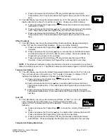
2.  At the end of the time out period, the system will enter Auto Off.  Power is turned off to

the heater and the LED Display will show a flashing “OFF ”.

Exiting Auto Off:  

Auto Off can be 

exited; returning to normal operation by:

1.

Pressing and releasing a Key (either of the 3 keys), or

2.  By turning the Power Switch OFF (“0”) and then back ON (“1”).

Summary of Contents for ST 45

Page 1: ...WORLDWIDE Operation and Maintenance Manual for the ST 45 ST 55 Soldering Systems P N 5050 0453 Rev D...

Page 2: ...Power Up 9 Heater Burn In 9 Tip Installation 10 Definitions 10 Quick Start Procedure 11 Operation 11 LED Display Normal Operation 12 LED Display Temperature Adjust Mode 12 Temperature Setback 13 Auto...

Page 3: ...pecifications System Power Source Power Requirements ST 45 or ST 55 Operates on 97 127 VAC 50 60Hz 90 Watts maximum at 115 VAC 60Hz ST 45E or ST 55E Operates on 197 253 VAC 50 60Hz 80 Watts maximum at...

Page 4: ...mmended by the manufacturer Directives de S curit Fran aise Langue Les pr cautions suivantes sont celles que le personnel doit comprendre et suivre lorsqu il utilise effectue la maintenance ou se sert...

Page 5: ...alle die in den Sicherheitsdatenblaettern des Herstellers ausgewiesenen Sicherheitsvorschriften eingehalten werden Misure di Sicurezza Italiana Lingua Le seguenti instruzioni sono misure di sicurezza...

Page 6: ...siga sempre todas as precau es de seguran a recomendadas pelo fabricante Guias de Consulta de Seguridad Esp nol Lenguaje Lo siguiente es precauciones de seguridad que el personal debe entender y debe...

Page 7: ...saTemp verktygselement och installerade spetsar r heta n r str mmen r p slagen och en tid efter att str mmen slagits av R R EJ element eller spets Risk f r br nnskador 4 PACE Spets och Verktygsh llare...

Page 8: ...and tighten by hand 6 Angle the power source so the operator can see the display easily and tighten the nuts with a wrench or pliers Tip Tool Stand The Tip Tool Stand can be mounted to the power sourc...

Page 9: ...tabilize at 315 C 600 F for 10 minutes 7 At the conclusion of the 10 minute period the heater temperature will increase to 427 C 800 F for 15 minutes 8 At the conclusion of the 15 minute time period t...

Page 10: ...Set Tip Temperature may be adjusted Temperature Display Impedance TDI Mode Stabilizes the tip temperature shown on the LED Display by ignoring minor temperature fluctuations Displayed changes in tempe...

Page 11: ...for use in standard soldering operations Simply perform the following Quick Start Procedure to begin using the system The systems can be stacked on each other for convenience and to preserve bench top...

Page 12: ...back mode perform any one of the following a Press and release a Key any of the 3 keys This is the preferred method b Wipe the hot handpiece tip on a wet sponge to lower the tip temperature c Turn the...

Page 13: ...lly activate after a preselected period 10 90 minutes of handpiece inactivity See the Customizing your System section for details on programming this feature 2 MANUAL ACTIVATION The operator can manua...

Page 14: ...then returns to normal operation If this occurs repeat steps 1 through 5 and enter the correct Password 5 The LED Display reads P Choose one of the following options a Press the Program Key to keep th...

Page 15: ...e Program Key to proceed to the next step NOTE If the attached handpiece is disconnected when the system is powered up any stored Offset Constant is reset to zero The Offset Constant must be entered a...

Page 16: ...the features and factory settings of each To change and or learn about any of these features refer to the applicable part of the Customizing Your System section of this manual Feature Factory Setting...

Page 17: ...to the applicable manuals for troubleshooting procedures pertinent to these handpieces Perform the procedures with the handpiece heater at room temperature If the heater is warm resistance readings wi...

Page 18: ...he replacement Heater Assembly with the keyway slot on the handle 5 Push the Heater Assembly fully into the handle 6 Replace the Heater Retaining Nut and tighten by hand Packing List Quantity Supplied...

Page 19: ...ters are normally warranted for a period of six 6 months from the date of receipt by the original purchaser PACE MAKES NO OTHER WARRANTY EXPRESSED OR IMPLIED AND MAKES NO WARRANTY OF MERCHANTABILITY O...

Page 20: ...products or services Arm Evac Flo D Sodr Mini Wave PACE SensaTemp Snap Vac SODRTEK SM Sodr X Tractor THERMO DRIVE ThermoFlo ThermoJet ThermoTweeze TOOLNET VisiFilter PERMAGROUND TM Tip Brite TM Auto...

Reviews: