background image

 3

INTRODUCTION

The following procedure will allow you to effectively calibrate your MBT 250/220
system to insure accuracy and maintain peak performance.

Perform the following procedure step by step, in sequence, to:

1. Alter Tip Temperature values.

2. Alter Tip Temperature Offset values.

3. Determine and/or alter feature status and defaults stored in the system.

4. Recalibrate the system for accuracy.

PROCEDURE

KEYLOCK OPTION

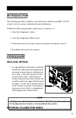
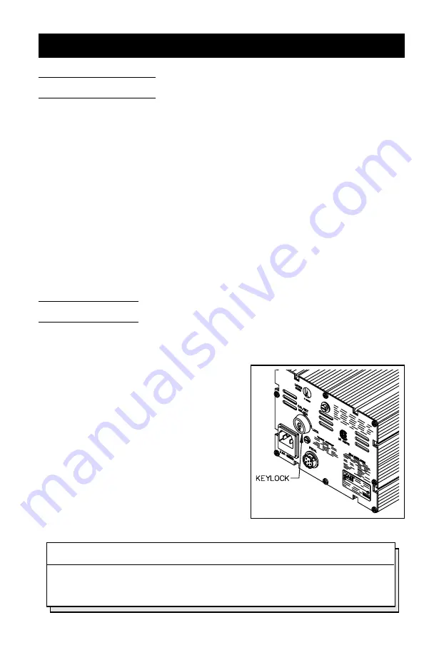
1. An optional KeyLock feature is available

from PACE which prevents unauthorized
alteration of stored data or calibration of
the system.  Check the rear panel of the
system power source.  If the KeyLock
feature is present there will be a KeyLock
switch located in the upper left portion of
the panel.  Use the key to turn the switch
to the “Unlock” position.  If the feature is
not present, there will be a round plastic
filler plug present at that location.

NOTE

The KeyLock switch must be turned to the “UNLOCK” position to alter any
of the data stored in memory or to recalibrate the system.

ENTERING CALIBRATION MODE

Summary of Contents for 6993-0133

Page 1: ...r local authorized PACE dealer or contact PACE directly at Telephone 301 490 9860 Fax 301 604 9215 PACEIncorporated 9893 Brewers Court Laurel MD 20723 1990 MBT 250 220 CALIBRATION KIT PACE P N 6993 01...

Page 2: ...ractor StripTweez SwaPlater ThermoBand ThermoPart ThermoPik ThermoJet ThermoTweez Thermo Drive VisiFilter The following are trademarks and or servicemarks of PACE Incorporated Laurel Maryland U S A an...

Page 3: ...PTION 1 An optional KeyLock feature is available from PACE which prevents unauthorized alteration of stored data or calibration of the system Check the rear panel of the system power source If the Key...

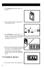
Page 4: ...the system LEDs will light TheTemperatureDisplaywillread 888 and change to read 1 X 5 Release the Tip Temperature Set and Scroll Down Keys The Temperature Display will now read CAL and only the three...

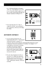
Page 5: ...meaning that Automatic Setback is turned off A readout of 1 thru 9 on the right side of the Digital Readout indicates time toAutomatic Setback in increments of 10 minutes For example S 3 would indicat...

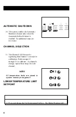
Page 6: ...matic Setback feature is enabled No additional steps are necessary CHANNEL SELECTION 11 The Channel 1 LED is now lit signifying that Channel 1 is ready for calibration Perform steps 12 through 21 to c...

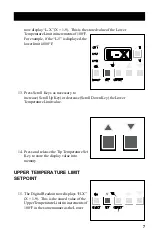
Page 7: ...ys as necessary to increase Scroll Up Key or decrease Scroll Down Key the Lower TemperatureLimitvalue 14 Press and release the Tip Temperature Set Key to store the display value into memory UPPER TEMP...

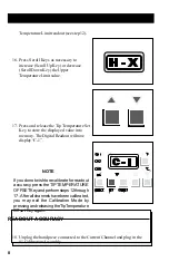
Page 8: ...he displayed value into memory TheDigitalReadoutwillnow display C 1 NOTE Ifyoudonotwishtorecalibrateforreadout accuracy press theTIPTEMPERATURE OFFSETKeyandperformsteps12through 17 Afterallchannelshav...

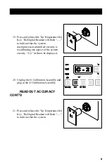
Page 9: ...processor controlled circuitry is recalibrating one aspect of the system circuity C 2 will now be displayed 20 Unplug the 1 Calibration Assembly and plug in the 2 CalibrationAssembly READOUT ACCURACY...

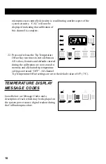
Page 10: ...to exit calibration All values features and defaults entered during the calibration are now stored in memory and all channel tip temperature settings are turned OFF All channel Tip Temperature Offset...

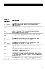
Page 11: ...t calibration module is inserted H X X 1 thru 9 Indicates the Current Channel is ready to accept new Upper Temperature Limit setpoint X X times 100 F L X X 1 thru 9 Indicates the Current Channel is re...

Page 12: ...12...

Reviews:

Related manuals for 6993-0133