background image


Attaching Tip & Tool Stand to MBT 350 


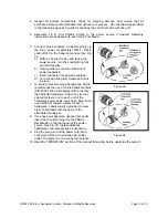
Attach the stand to the power source, using the following procedure. Refer to illustration. 
 
1. Insert the 2 enclosed hex head Mounting Screws into the slot on the side of the Power Source. Some 
kits may contain 4 mounting screws; 2 with small heads and 2 with large heads. Use the 2 screws that fit 
properly in the slot. Also, some Power Source cases have more than 1 slot; use the lower slot. 
 

Figure 4

2. Position the Mounting Screws to the rear of the power source and 
spaced approximately 2 inches apart. Refer to illustration. 
 
3. Place the Tip & Tool Stand beside the power source. Insert ends 
of the 2 Mounting Screws into the 2 adjacent Tip & Tool 
Stand mounting holes. 
 
4. Install a Thumb Nut onto the end of each Mounting Screw. Tighten 
Thumb Nuts to secure the Tip & Tool Stand in position. 
You may wish to set the Power Source on its side and remove the 
drip tray to ease installation of the Thumb Nut. 
5. Additional Tip & Tool Stands or “cubby’s” may be secured to each 
other by aligning mounting holes on stand sides. Use hex head 
screws and thumb nuts to mount cubbys together.  
 

Optional Instant-Setback Cubby  
 

The optional Instant SetBack Cubby is available for use with the MBT 350 and will only function with the 
TD-100 handpiece. When connected, it automatically puts the system into Setback mode when the TD-
100 is placed in the cubby. The Instant Setback Cubby will only function with the TD-100 Handpiece. The 
MBT 350 is capable of using two Instant Setback Cubbys at the same time. The instant SetBack 
receptacles are located on the back panel. See figure 3. The instant setback cubby's function is to protect 
tips, not power off the system.  Instant setback is a feature that lowers the temperature to 350°F after 45 
seconds of inactivity. At 350°F the solder has solidified so any iron erosion on the tips ceases, protecting 
the tip.  

 
Tip Removal 


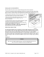
Never remove a heated tip using bare hands.  Use the Hot Grip Rubber Pad or Tip Tool.   

Never use a wrench or pliers when removing a handpiece tips.


WARNING 


©2005 PACE Inc., Annapolis Junction, Maryland All Rights Reserved                                                     Page 11 of 19 


Summary of Contents for 5050-0552

Page 1: ...Operation and Maintenance Manual for the PACE MBT 350 Digital Soldering Desoldering System P N 5050 0552 Rev A TWF05 05...

Page 2: ...LED Operation 13 Operation 13 Accessing Programming Menu 16 Password Menu 13 Setting Temperature C F 13 Set Upper Limit 14 Set Lower Limit 14 Setback Time 14 Set Auto Off 14 Scan Enable Disable 14 Set...

Page 3: ...version system bears the CE Conformity Marking which assures the user that it conforms to all the requirements of EU directive EMC 89 336 EEC 73 23 EEC Specifications POWER REQUIREMENTS MBT 350 Versi...

Page 4: ...C to 50 C 32 F to 120 F Storage Temperature 40 C to 100 C 40 F to 212 F Capabilities All capabilities are dependent upon the use of the appropriate Functional Accessories or Work Aids refer to Basic O...

Page 5: ...Turns system ON 1 and OFF 0 controls input power to the system 7 PRESSURE ADJUSTMENT Controls variable airflow pressure delivery 8 PRESSURE PORT Quick connect fitting with provides airflow for Mini T...

Page 6: ...d to which a ground cable can be connected from the work piece or work surface as part of a static control program 14 AC POWER RECEPTACLE FUSE HOLDER Receptacle for providing power to the system from...

Page 7: ...t when the handpiece is powered on and for a period of time after power off DO NOT touch either the heater or the tip Severe burns may result 4 PACE Tip Tool Stands and handpiece cubbies are designed...

Page 8: ...ate injury May also be used to alert personnel to conditions procedures and practices which if not observed could result in damage to or destruction of the product or other equipment WARNING Used to d...

Page 9: ...eral safety precautions that personnel must understand and follow when using or servicing this product These precautions may or may not be included elsewhere in this manual Safety Electrical Requireme...

Page 10: ...ock in place 7 To avoid confusion among handpieces PACE recommends the use of colored cable markers Figure 3a P N 6993 0136 Cable Marker Kit to identify the particular handpiece Attach any two like co...

Page 11: ...l Stands or cubby s may be secured to each other by aligning mounting holes on stand sides Use hex head screws and thumb nuts to mount cubbys together Optional Instant Setback Cubby The optional Insta...

Page 12: ...display an instruction to enter the password Enter a four digit number selected using the scroll up down keys on the system front panel when a setting change is attempted Programming Menu The interfa...

Page 13: ...disable the display contrast and backlight settings To access set up mode press and hold the PROGRAM Key while powering on unit Release key when Software Version appears Pressing the PROGRAM Key will...

Page 14: ...ess and release the Scroll Down Key to decrease or enter 00 to disable the stored Temperature Setback time Press and release the PROGRAM Key to proceed to the next step The LED Display now shows the s...

Page 15: ...channel 1 Or press the PROGRAM Key to move the next channel After a period of 10 seconds of inactivity the display will return to normal operation Accessing Calibration Menu Press and hold the PROGRA...

Page 16: ...user to delete the hello message Press the UP key to change the hello message or press the DOWN arrow key to exit and return the normal operation mode Corrective Maintenance Power Source Refer to the...

Page 17: ...14 0 0 1 1 9 Cable Marker Kit 6993 0136 P1 0 0 1 1 10 Angle Bracket Kit 6018 0097 P1 0 0 1 1 11 PACE Screwdriver 1100 0230 0 0 1 1 12 SX 80 Blue Connector Kit 6993 0266 P1 0 0 1 1 13 MT 100 Blue Conne...

Page 18: ...corporated Annapolis Junction Maryland U S A ARM EVAC FLO D SODR MINIWAVE PACE SENSATEMP SNAP VAC SODRTEK SODR X TRACTOR THERMOFLO THERMOJET THERMOTWEEZ VISIFILTER THERMO DRIVE and TOOLNET PACE produc...

Reviews: