background image

6

The following are safety precautions which personnel must understand and follow
when using or servicing this product.

1. To prevent personnel injury, adhere to safety guidelines in accordance

with OSHA and other applicable safety standards.

2. SensaTemp handpiece heaters and installed tips are hot when the

handpiece is powered on.  DO NOT touch either the heater or the tip.
Severe burns may result.

3. The enclosed Tip & Tool Stand has been designed specifically for use

with the your handpiece and houses it in a manner which protects the
user from accidental burns.  Always store the handpiece in its Tip & Tool
Stand.

4. Always use this system in a well ventilated area.  A fume extraction

system such as those available from PACE are highly recommended to
help protect personnel from solder flux fumes.

5. Exercise proper precautions when using soldering materials (e.g.,

fluxes).  Refer to the Material Safety Data Sheet (MSDS) supplied with
each material and adhere to all safety precautions recommended by the
manufacturer.

6. The following safety precautions cover use of the PS 50 Prep-Set system.

a) The PS-50 Prep-Set heater and installed Pot-Tip (+ solder) or Preheat

Plate are hot when the Prep-Set is powered on and for a period of
time after power off.  DO NOT touch either the heater, Preheat Plate,
Pot-Tip or solder.  Severe burns may result.

b) Insure that the rubber heat shield (covering the heater) is in place.

Never operate the system without the shield in place.  Severe burns
may result.

c) Turn the Power Switch off and allow the installed solder Pot-Tip or

Preheat Plate to cool before changing.  Never touch a hot Pot-Tip or
Preheat Plate with bare hands.

7. POTENTIAL SHOCK HAZARD - Repair procedures on this product

should be performed by Qualified Service Personnel only.  Line voltage
parts will be exposed when the equipment is disassembled.  Service
personnel must avoid contact with these parts when troubleshooting the
system.

Safety

Summary of Contents for 20A

Page 1: ...Operation Maintenance Manual ST 20A Systems ...

Page 2: ...Vac PRC PRINT Pro Evac Redi Rak ResisTweez SensaTemp SMR Snap Vac Sodr Pen Sodr X Tractor SR 3 SR 4 ST StripTweez SwaPlater ThermoBand Thermo Drive ThermoJet ThermoPart ThermoPik ThermoTweez Tip Evac VisiFilter The following are trademarks and or servicemarks of PACE Incorporated Laurel Maryland U S A and may only be used to identify genuine PACE products or services Auto Off Cubby Vac Datastore D...

Page 3: ...ations e g applications requiring use of large SMT tips PACE recommends that the user read and fully understand all of the Operation portion of this manual in order to utilize the features of this system ST 20A TT and ST 20A PS systems are shipped with an additional manual which should be read and fully understood before operating those systems 1 For any questions regarding this Operation Maintena...

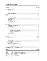
Page 4: ...perature Control 16 Temperature Dial Lock 16 Tip Offset 16 LED Operation 17 Auto Off Safety System 17 Calibration 18 Corrective Maintenance 19 Power Source 19 Handpieces 19 Sodr Pen Heater Replacement 20 Replacement Parts 21 SP 1A SP 2A Handpieces 21 Accessory Tray Items 22 Optional Accessory Items 22 Manual Improvement Comment Form 25 TABLE PAGE Table I Single Point Tips 9 Table II Power Source C...

Page 5: ...ations ST 20A TT Consists of the PPS 15 power source 115 VAC 230 VAC or 100 VAC version TT 65 ThermoTweez handpiece TT Tip Tool Stand and accessory kit The standard TT 65 ThermoTweez handpiece provides safe one handed removal of a wide variety of components PLCCs SOICs PQFPs BQFPs SMT Connectors etc in a matter of seconds Its lowtemperature high capacity heating can remove even the largest compone...

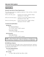
Page 6: ...pieces Tip Temperature Range 93 C to 482 C 200 F to 900 F nominal Temperature Stability 1 1 C 2 F at idle from set tip temp PS 50 Prep Set Temperature Range 93 C to 371 C 200 F to 700 F nominal NOTE Actual minimum and maximum Operating Tip Temperatures may vary depending on Handpiece or PS 50 Tip Selection and application EOS ESD Specifications The specifications shown below apply except on Soft G...

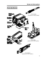
Page 7: ...5 Parts Identification General Information SP 2A Handpiece standard with ST 20A SP Systems TT 65 Handpiece standard with ST 20A TT Systems PS 50 PrepSet standard with ST 20A PS Systems ...

Page 8: ... fluxes Refer to the Material Safety Data Sheet MSDS supplied with each material and adhere to all safety precautions recommended by the manufacturer 6 The following safety precautions cover use of the PS 50 Prep Set system a The PS 50 Prep Set heater and installed Pot Tip solder or Preheat Plate are hot when the Prep Set is powered on and for a period of time after power off DO NOT touch either t...

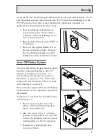
Page 9: ...orner indentations Refer to illustration below Auto Off Safety System The Auto Off Safety System removes power from the connected handpiece after 90 minutes of handpiece inactivity As received from the factory the feature is Disabled 2 position The LED on the front panel will illuminate Yellow in color with handpiece connected Refer to the description of the Auto Off Safety System detailed in the ...

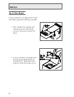
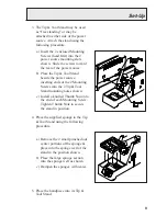
Page 10: ...and perform the following procedure 1 Place 4 Rubber Feet packed with small accessories on the bottom corners of any enclosed Tip Tool Stand 2 If your system has been shipped with a TT Tip Tool Stand for TT 65 ThermoTweez install the bracket using the enclosed mounting screws ...

Page 11: ...ource inserting ends of the 2 Mounting Screws into the 2 Tip Tool Stand mounting holes shown c Install a knurled Thumb Nut onto the end of each Mounting Screw Tighten Thumb Nuts to secure the stand in position 4 Place the supplied sponge in the Tip Tool Stand using the following procedure a Remove the 2 small punched out center portions of the sponge place into the sponge well of the stand in the ...

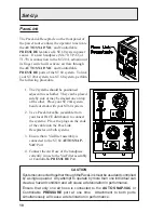
Page 12: ...A system beside or stack with your ST 60 system 2 Use a PaceLink cable available from your local PACE distributor to connect the systems Place the plugs on the ends of the cable into the PaceLink Receptacles on both systems 3 Ensure that a VisiFilter assembly is connected to the ST 60 AUTO SNAP VAC Port 4 Connect the Air Hose of the handpiece currently in use to the VisiFilter assembly or Controll...

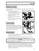
Page 13: ...Hose Feed Thru holes located on the bottom of the power source System Power Up 1 Insert the female end of the power cord into the AC Power Receptacle at the rear panel of the power source 2 Plug the prong end male end of the power cord into a 3 wire grounded AC supply receptacle The system is now ready for operation CAUTION To insure operator safety the AC supply receptacle must be checked for pro...

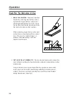
Page 14: ...there is maximum surface contact area The use of a solder bridge to enhance thermal linkage will also improve heat transfer Operation 2 TIP ACCESS VISIBILITY The tip selected must easily contact the joint without touching the board substrate adjacent components or other solder joints Longer thinner more tapered tips allow the operator to more easily access and view the solder joint during solderin...

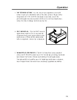
Page 15: ...VAL Tips for SMT removal applications must fit over or around the component body and contact all the solder joints at once When all the solder joints reflow completely remove the component 5 SODR PEN HANDPIECES The SP 2A Sodr Pen comes standard with your ST 20A SP system uses 3 16 shank tips providing maximum heat transfer for Surface Mount and multilayer board applications The optional SP 1A Sodr...

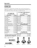
Page 16: ...1 0361 3 32 Chisel 1121 0529 1 32 Conical 1121 0336 1 8 Chisel 1121 0530 1 16 Chisel MicroFine 1121 0349 3 16 Chisel 1121 0531 1 16 Chisel 1121 0335 Single Sided Chisel 1121 0532 1 16 Chisel High Capacity 1121 0414 3 16 SHANK THERMO DRIVE TIPS for SP 2A Sodr Pen 1 16 Chisel Extended Reach 1121 0499 1 16 Bent Chisel Ext Reach 1121 0500 1 64 Conical 1121 0516 3 32 Chisel 1121 0360 1 64 Bent Conical ...

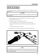
Page 17: ... hot CAUTION Hold the handpiece with the heater pointed at an angle up to prevent injury to personnel 1 Select the proper tip for your application Refer to Table I or the PACE Tip Applications Catalog 2 Install the selected tip in the following manner a Hold the handpiece with the heater up at an angle heater hot b Insert the Tip all the way into the heater bore using the supplied Tip Tool c Gentl...

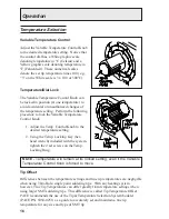
Page 18: ...erature Control Knob 1 Adjust the Temp Control Knob to the desired temperature setting 2 Using the Temp Locking Key hex head wrench included with the system tighten the 2 set screws on the Temp Locking Ring NOTE Temperature will remain at its locked setting even if the Variable Temperature Control Knob is forced to move Tip Offset Differences between the temperature settings and true tip temperatu...

Page 19: ...ter cold or the Variable Temperature Control setting is increased LED Flashing Indicates that the set tip temperature as set on the Variable Temperature Control has been reached Power to the handpiece is cycling Off and On to maintain set temperature LED Off No power is being delivered to the handpiece heater This condition is evident if the Variable Temperature Control setting is decreased If the...

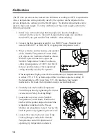
Page 20: ...ark as shown With the system turned on adjust the Variable Temperature Control to obtain a stable tip temperature of 300 C for PACE factory specifications or the temperature setting normally used by the operator If the temperature displayed on the Process Monitor or temperature meter is within 5 C 10 F perform steps 4 thru 6 to obtain a precise reading If the temperature is off by more than 5 C th...

Page 21: ...er source Use a meter to check resistance across the handpiece connector plug pins as outlined in the Checkout Procedure column Table III Heater Assembly Checkout Procedures Symptom Checkout Procedure Cause Solution Heater Specifications No heat Check resistance Pin 2 to Pin 5 Refer to Heater Specifications column If resistance is high Open Heater Replace Heater Assembly SP 1A SP 2A SX 70 TP 65 10...

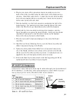
Page 22: ...toward the Heater Assembly to expose the Insulator Slide the Insulator back toward the Handle end to expose the 5 lead wire connections between the Heater Assembly and the Cable Assembly 4 Disconnect the 5 Heater Assembly leads Remove the Insulator from the Cable Assembly leads Discard the old Heater Assembly and Insulator 5 Feed the Cable Assembly leads back through the replacement Insulator with...

Page 23: ...ck through the handpiece until the Heater Assembly rests against the plastic Handle Gently twist the Heater Assembly if necessary to slide the narrow notches on the Insulator between the tabs on the inside of the Handle 9 Place the new metal Compression Spring over the end of the Heater Assembly 10 Install the new Heater Retaining Nut to secure the Heater Assembly and rubber Compression Spring to ...

Page 24: ...100 115 VAC 1332 0094 1 0 1 0 1 0 5 Power Supply Cord 230 VAC 1332 0093 0 1 0 1 0 1 6 SP Tip Tool Stand 6019 0043 1 1 0 0 0 0 7 TT Tip Tool Stand 6019 0046 0 0 1 1 0 0 8 Sponge for Tip Tool Stand 4021 0008 P3 1 1 1 1 0 0 9 Wire Brush 3 16 inch diameter 1127 0014 P5 1 1 1 1 0 0 10 Tip Tool 1100 0206 1 1 1 1 0 0 11 Hex Wrench Temp Locking Key 1 1 1 1 1 1 12 Rubber Foot 4 4 4 4 0 0 13 Screw 8 32 x 1 ...

Page 25: ...J 1159 0217 2 SP 1A Sodr Pen 37 Watts 6025 0013 P1 3 Wire Brush 1 8 inch diameter 1127 0006 P5 4 AdapTip Kit for SP 2A Sodr Pen 1360 0083 P1 5 Tip Temperature Selection System Booklet 5050 0251 6 V SX Vacuum Option solder extraction 6993 0131 7 SX Tip Tool Stand for air handpieces 6019 0044 8 Tip Redi Rak 6021 0007 9 SMD Tip Accessory Kit 6993 0170 10 Replacement Fiber Filler 1127 0013 P2 11 Repla...

Page 26: ...24 ...
Page 27: ...d form to PACE Incorporated Applications Engineering Fax 301 604 8782 9893 Brewers Court Laurel MD 20723 1990 U S A Document 5050 0355 Rev C Date of Submission Nature of Change Identify page and paragraph and include proposed rewrite if possible Reason for Recommendation Name of Submitter Company or Organization Mailing Address Telephone Voice Fax Thank you for your comments They are greatly appre...

Reviews: