


Section 3
Dimensions
3-8
12/11
DETAIL VIEWS
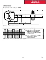
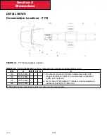
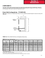
Crossmember Locations – T170
FIGURE 3-7.
T170 Crossmember Location
TABLE 3-6
T170 Cross member.
Location: measured from front axle centerlines [inches (mm)]
WB
A
CB
C
D
E
153
101 .8 (2585)
Y
1 .) For without a square end of frame crossmember with an AF
range of 80 (2032)to 125(3175) a crossmember is installed at:
E=WB+64 .4”(1636mm)
2 .) For AF range of 126 (3200) to 173(4394) a 2nd crossmember is
installed at: E=WB+112 .4”(2855 mm)
162
101 .8 (2585)
Y
176
101 .8 (2585)
Y
188
101 .8 (2585)
Y
Y SPL100 Driveline center bearing (CB) is mounted on this cross member
Summary of Contents for Kenworth T170 2011
Page 1: ...Kenworth T170 T270 T370 and Hybrid 2011 Body Builders Manual...
Page 2: ......
Page 10: ...12 11 Section 1 Introduction Page Intentionally Left Blank...
Page 52: ...Section 3 Dimensions 3 34 12 11 Automatic Transmission Allison 3000RDS...
Page 53: ...3 35 Section 3 Dimensions 12 11 Manual Transmission...
Page 111: ...Section 5 Frame Layouts 5 40 12 11 Page Intentionally Left Blank...
Page 120: ...Section 6 Body Mounting 6 9 12 11 Page Intentionally Left Blank...
Page 128: ...Section 7 Frame Modifications 7 8 12 11 Page Intentionally Left Blank...
Page 165: ...Section 8 Electrical 8 37 12 11 FIGURE 8 31 Cab Load Center mPDC...
Page 170: ...Section 8 Electrical 8 42 12 11 Page Intentionally Left Blank...
Page 179: ...12 11 Kenworth Truck Company P O Box 1000 Kirkland WA 98083 425 828 5000...


