


Section 9
Routing
9-4
12/11
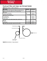
Routing of Wires and Hoses near Exhaust System
TABLE 9-1.
Exhaust – System Clearance
Description
Shielded
Unshielded
Coolant hoses, HVAC hoses and tubing, and electrical wires
within 15” of the turbo and/or over 15” from the turbo
2” minimum
3” minimum
Fuel hoses
within 15” of the turbo
over 15” from the turbo
n/a
2” minimum
4” minimum
3” minimum
Fuel tanks and hydraulic tanks
crossing tank
parallel to tank
end of tank
aluminum/ceramic-coated exhaust pipe crossing tank
n/a
n/a
n/a
n/a
2” minimum
2” minimum
1” minimum
1 .5” minimum
Air hose
nylon
wire braid
3” minimum
2” minimum
8” minimum
3” minimum
Electrical wires (located at or down line of the DPF)
3” minimum 8” minimum
Exhaust system
(pipe, muffler)
Heatshield (or blanket)
Component
Shielded dimension
Unshielded dimension
FIGURE 9-5.
Definition of measurements.
Summary of Contents for Kenworth T170 2011
Page 1: ...Kenworth T170 T270 T370 and Hybrid 2011 Body Builders Manual...
Page 2: ......
Page 10: ...12 11 Section 1 Introduction Page Intentionally Left Blank...
Page 52: ...Section 3 Dimensions 3 34 12 11 Automatic Transmission Allison 3000RDS...
Page 53: ...3 35 Section 3 Dimensions 12 11 Manual Transmission...
Page 111: ...Section 5 Frame Layouts 5 40 12 11 Page Intentionally Left Blank...
Page 120: ...Section 6 Body Mounting 6 9 12 11 Page Intentionally Left Blank...
Page 128: ...Section 7 Frame Modifications 7 8 12 11 Page Intentionally Left Blank...
Page 165: ...Section 8 Electrical 8 37 12 11 FIGURE 8 31 Cab Load Center mPDC...
Page 170: ...Section 8 Electrical 8 42 12 11 Page Intentionally Left Blank...
Page 179: ...12 11 Kenworth Truck Company P O Box 1000 Kirkland WA 98083 425 828 5000...


