Paccar Winch BRADEN BA5A Installation Maintenance And Service Manual Download Page 18

Crane inspection reports as well as records of preven-
tive maintenance, repairs and modifications to hoists
should be available and accessible for a minimum of
four years.  These records should include, but not be
limited to, hoist model and serial number, name and
employer of repair/inspection technician, date and
description of preventive maintenance, functional test
reports and repairs.

To provide customers with qualified outlets for hoist
service and repairs, BRADEN has established author-

ized Service Centers.  These Service Centers have
factory trained service technicians, up-to-date service
information, extensive parts inventories, complete test-
ing facilities, and are audited by BRADEN on a regular
basis for compliance.  

BRADEN strongly recom-

mends the use of BRADEN authorized Service
Centers

for maintenance, repair and inspection of

BRADEN products.  Contact the Braden Product
Support Department at 918-251-8511 for the names of
current authorized Service Centers.

Name of Service Company

Approved by BRADEN for handling personnel 

if used and maintained in accordance with BRADEN 

Recommendations For Personnel Handling Hoists

Hoist Model No.:

_______________________________

Hoist Serial No.:

_______________________________

Date of Inspection:

_______________________________

Work Order/Job No.: _______________________________
Inspector’s Name:

_______________________________

For a copy of recommendations call or write: BRADEN 
PO Box 547, Broken Arrow, OK, 74012, USA (918) 251-8511

INSPECTION RECORDS & RETENTION

TEAR DOWN INSPECTION

16

Any Hoist that has NOT been subject to regular oil
sample analysis should undergo a tear down
inspection on an annual (12 month) basis.

Also, if a

hoist has an unknown history of repair and/or mainte-
nance, it is recommended that the hoist undergo a tear
down inspection prior to it being placed into service.

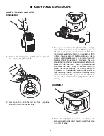
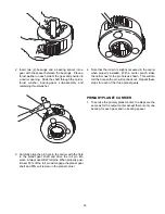
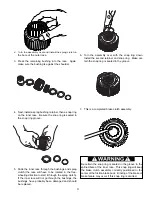
A tear down inspection should include the hoist being
completely disassembled, cleaned and inspected and
replacement of all worn, cracked, corroded or distorted
parts such as pins, bearings, shafts, gears, brake
rotors, brake plates, drum and base.  Refer to the appli-
cable BRADEN Service Manual for more details.  All
seals and o-rings should be replaced during a tear
down inspection.

Any deficiencies, such as those listed above shall
be corrected immediately.

All of the following operations must be performed
before the hoist is placed back in service:

The rebuilt hoist must be line pull tested to the rated
load of the hoist (hoist rating will vary with motor, gear
ratio and drum options) with a dynamometer or equiv-
alent measuring device.  This test load should be the
maximum rating for the hoist for the specific applica-
tion, not the reduced rating for personnel lifting.

The hoist must be dynamically tested by rotating the
drum several times, in both the hoisting and lowering
directions, while under a load of at least 30% of the
hoist lifting capacity.  Check for smooth operation dur-
ing this procedure.

After inspection or rebuild and testing, a new certificate
for personnel handling will be issued by the inspector/
service technician effective on the date the hoist is
placed back in service.

Sample inspection certificate

Summary of Contents for BRADEN BA5A

Page 1: ...tenance and Service Manual PACRWINCH DIVISION P O BOX 547 BROKEN ARROW OK U S A 74013 PHONE 918 251 8511 FAX 918 259 1575 www paccarwinch com LIT2381 11 2009 PRINTED IN U S A COPYRIGHT 2009 PACCAR WIN...

Page 2: ......

Page 3: ...YSIS 17 TROUBLESHOOTING 18 SERVICE PRECAUTIONS 21 WINCH DISASSEMBLY 22 WINCH CROSS SECTION 23 WINCH ASSEMBLY 24 PLANET CARRIER SERVICE 26 BRAKE CLUTCH SERVICE 28 AIR MOTOR SERVICE 30 BAND BRAKE ADJUST...

Page 4: ...t Some pictures in this manual may show typical details or attachments that are different from your hoist Also some components may have been removed for illustrative purposes Whenever a question arise...

Page 5: ...cts 4 An equipment warm up procedure is recommended for all start ups and essential at ambient tempera tures below 40 4 C Refer to Warm up Procedure listed in the Preventive Maintenance section of thi...

Page 6: ...y in the direction required to spool cable onto the drum i e lift a load then immediately locks the hoist gear train to the mechanical brake when the hoist is stopped holding the load in place Top Lay...

Page 7: ...um Layer All wraps of wire rope on the same level between drum flanges Freeboard The amount of drum flange that is exposed radially past the last layer of wire rope Minimum freeboard varies with the r...

Page 8: ...gear shaft between the motor and the primary sun gear It will allow the shaft to turn freely in the direction to raise a load and lock up to force the brake discs to turn with the shaft in the direct...

Page 9: ...ture trap and provide 20 micron filtration If the rated per formance of the motor is to be obtained all valves and pipework must be of adequate size For short pipe runs up to 2 meters the supply line...

Page 10: ...f the wedge as shown in figure 2 Using a hammer and brass drift drive the wedge as deep into the pocket as possible to ensure it is fully seated and no further movement is detected Check to ensure the...

Page 11: ...9 Correct Installation Incorrect Installations Wedge not fully seated Wedge pulled too far through anchor pocket Wire rope not tight against wedge Wedge may be too large Dead end of wire rope and or...

Page 12: ...uipment operators should be completely familiar with the overall operation of the piece of equipment on which the hoist is mounted i e crane truck crane etc If you have any questions concern ing the s...

Page 13: ...hoist does not operate smoothly or makes any unusual sounds the source of the problem should be identified and corrected before any attempt is made to lift the load 6 When lifting loads we recommend t...

Page 14: ...in the air reaching the motor 5 The air line lubricator should be replenished as required and set to give 6 to 8 drops per minute If operation is intermittent double the rate to 12 to 16 drops per mi...

Page 15: ...ticles that impede reliable and safe operation of the brake clutch and erode bearings and seals Failure to change gear oil at recommended intervals may contribute to intermittent brake slip page loss...

Page 16: ...HETIC OR EQUIVALENT oC 40 30 20 10 0 10 20 30 40 50 oC NOTE SHADED TEMPERATURE RANGE IN THE CHART ABOVE NOT RECOMMENDED FOR SEVERE APPLICATIONS SUCH AS OFFSHORE CRANES SUSTAINED FAST DUTY CYCLES OR FR...

Page 17: ...ellus 100 Tellus 37 B P Energol HL175 Energol HLP65 Esso Nuto H 64 Fanox 38 Regent Regal PE RO Rando A Castrol Hyspin 175 Hyspin 70 Mobil D T E Extra Heavy Almo Oil NO 1 For extreme ambient temperatur...

Page 18: ...INSPECTION RECORDS RETENTION TEAR DOWN INSPECTION 16 Any Hoist that has NOT been subject to regular oil sample analysis should undergo a tear down inspection on an annual 12 month basis Also if a hoi...

Page 19: ...d then take the oil sample from the drain port as soon as possible Do not take the sample from the first oil out the drain port Take a sample from the mid stream flow of the oil to obtain an accurate...

Page 20: ...er will not hold pressure seal is defective Disassemble and inspect the brake Ensure proper number of brake plates and friction discs are used Adjust band brake as defined in Band Brake Adjustment sec...

Page 21: ...described in the Brake Clutch D The winch will not hoist the rated load 1 The winch may be mounted on an uneven or flexible surface which causes distortion of the winch base and binding of the gear tr...

Page 22: ...time the load is removed Then when winding is resumed the rope has a tendency to criss cross and overlap on the drum The result is apt to be a flattened and crushed rope 4 The winch may have been ove...

Page 23: ...il seals and O rings Before reassembly inspect all machined surfaces for excessive wear or damage Lubricate all O rings and the inside surface of oil seals with gear oil or general purpose grease prio...

Page 24: ...ve bolts 219 which attach the brake cylinder to the motor side plate and remove brake cylinder 10 Remove bolts which attach the motor side plate 19 to the base angles and remove the motor side plate S...

Page 25: ...23 THIS PAGE INTENTIONALLY LEFT BLANK...

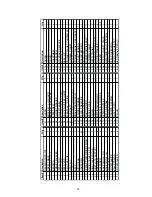
Page 26: ...24 WINCH CROSS SECTION...

Page 27: ...IFICE ASSY 1 200 BRAKE PARTS GROUP 1 201 CYLINDER BRAKE 1 202 PLATE PRESSURE 1 203 BRAKE SPRING 12 204 FRICTION DISC 3 205 BRAKE PLATE 4 206 O RING 1 207 O RING 1 208 RETAINING RING INT 1 209 ADAPTER...

Page 28: ...sun gear 7 10 Apply general purpose grease to the drum closure o ring 11 and install the drum closure into the winch drum 11 Bolt the motor end side plate to base angles The guard bracket will attach...

Page 29: ...ines of the sprag clutch inner race 21 Lift the motor using both an eye bolt and pipe fitting in the motor exhaust port 1 11 NPT ensure full engagement of pipe threads or remove 2 bolts from the motor...

Page 30: ...orrosion discol oration material displacement or abnormal wear the bearing should be replaced Likewise the cage should be inspected for unusual wear or deformation particularly the cage bars If there...

Page 31: ...place Always use NEW roll pins When properly posi tioned 50 of the roll pin will engage the planet gear shaft and 50 will remain in the planet carrier 4 Note that the roll pin is slightly recessed in...

Page 32: ...ng is damaged or shows excessive wear there is no need for further disassembly If disassembly is necessary remove the bushing according to the procedure covered in Step No three 3 All brake clutch ass...

Page 33: ...g direction to start it through the sprag clutch If the inner race will not go through the bushings the bushings have probably been damaged and should be replaced 6 Turn the assembly over with the sna...

Page 34: ...the pivot pin 29 6 Inspect the clearance of the pivot pins 29 in queen rod 30 and king rod 12 Inspect the gudgeon pin in both the piston and all rods Check for wear on the main crankshaft 20A 20B and...

Page 35: ...180 degrees to allow valve to be fitted 10 Lubricate valve 2 and Inside Bore of Housing 3 11 Rebuild the valve assembly in the reverse order Check it rotates freely Fit valve assembly on to the motor...

Page 36: ...link item 804 to 1 19 1 29 in 30 33 mm 3 Apply brake adjust as needed to allow handle to lock in place with a hard pull 4 Release brake and adjust set screw item 808 to allow the band brake to drop a...

Reviews: