Product Configuration (cont.)
Installation Steps
Set the dip switches for your vehicle, and the camera inputs which you wish to activate.
Set the dip switches BEFORE connecting the module to power. If a change is made to the dip switches, disconnect then
reconnect the module, for the changes to take effect.
Remove the factory radio (display) and disconnect the factory harness.
Connect the BCI-FD21-H01 harness to the back of the factory radio (display) and reconnect factory harness to the mating
connector on this harness.
Connect the aftermarket cameras to the appropriate inputs on the BCI-FD21-H02 harness.
Connect 12-volt power and ground to your aftermarket cameras. (Note: use of this 12v output can extend the life of your
cameras as it only powers the cameras when needed)
Brown Wire
= 12 Volt + (2A)
Black Wire
= Ground
Connect both BCI-FD21 harnesses to the BCI-FD21.
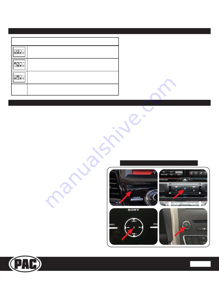
Program the BCI-FD21 to the vehicle:
• Turn the key to the RUN position.
• Once the radio is fully “booted” and on a source screen,
press and hold the Power button of the radio for 10
seconds.
• The radio will program and restart in approximately 15
seconds. Once restarted, the radio will “boot-up”, wait for
1-2 minutes until the radio is fully “booted” and on a
source screen.
• To finish programming turn off the ignition, open the
driver’s door and wait until the radio is completely off (1-2
minutes).
• Turn on the ignition and test camera functions.
1.
Note:
In order for the BCI-FD21 to function, at least one
camera input must be set ON in Camera Input Configuration.
2.
3.
4.
5.
6.
7.
Vehicle Configuration Procedure:
Set dip switches per vehicle model according to chart.
Be advised that some vehicle models can have different
dip switch configurations based on the model year.
To verify if you have selected the correct dip switch
configuration for your vehicle, activate one of the turn
signals and watch the BLUE LED on the BCI-FD21.
The LED should illuminate while the turn signal is active.
If it does not, try another dip switch configuration until
you find one where the LED illuminates while the turn
signal is active.
Page 2
Rev. 071
9
16
PAC | Ph. 866-931-8021 | [email protected]
© 2016 AAMP Global
www.pac-audio.com
Camera Interface for Select Ford & Lincoln Vehicles with
MyFord Touch or MyLincoln Touch 8.4” Radios
BCI-FD21
Ford C-Max, Escape and Focus
Ford Expedition, Flex, Lincoln MKS and MKT
Ford Edge, F150, Fusion, Mustang, Raptor and Lincoln MKX
Vehicle Configuration (Dips 1, 2, 3)
ON
1 2 3
ON
1 2 3
ON
1 2 3
4
ON = Cannot view OE rear camera image while in
motion (up to 7mph). OFF = Can view OE rear cam in motion.
4
4
Dip 4
Power Button Location on 4 Different Vehicles


