background image

"BLT 160” 

ユーザーマニュアル

/ USER MANUAL 


改訂版

. n° 5 - 19/07/2011


P.B.M.

 S.r.l

 via Barella, Z.I. - VIGNOLA ( MO ) ITALIA 

Tel. + 39 059 770 53 11 - Fax + 39 059 770 53 00 

http://www.gruppopbm.it  e-mail[email protected]

ファイル

: MU001033GJ_BLT160_GB_JAP rev5_190711.doc


P. 2


Discharger BLT160 

INSTALLATION / USE / OPERATION 


The BLT160 device is a BATTERY DISCHARGER designed for connection to a freestanding battery  charger, 
which can manage completely automatic charge and discharge cycles successively on the same battery. 
 
The main components of the discharger are: 


Fanned passive dissipator unit 


Fanned active dissipator unit for constant current 


Main control card AP211 


Active components driver cards AP208 


DC contactors for engaging passive loads and battery charger 


WARNING!  
If  combined  with  a  battery  charger,  it  is  necessary  for  this  latter  to  feature  the 
AUTOSTART function, which is enabled on battery connection. 


ATTENTION 
The USB connection is foreseen only for technical service.  
A use in the industrial sector could entail a communication cut with the service PC. 


ATTENTION! 
The charger connected to the BLT must supply current up to 160 A. 
The possible connection of a charger with higher current, can damage the BLT 

 
To use the BLT160 discharger, all safety prescriptions must be adhered to.  

 
Obligations of the “user”:

 Conforming to the user manual, the user is responsible for the proper installation of 

the device in appropriate sites following the indications given in this manual. 


Summary of Contents for BLT160

Page 1: ...el 39 059 770 53 11 Fax 39 059 770 53 00 http www gruppopbm it e mail pbm gruppopbm it MU001033GJ_BLT160_GB_JAP rev5_190711 doc DISCHARGER BLT160 VERSION WITH CARD AP211 AP211 USER MANUAL READ THE FOL...

Page 2: ...ctive components driver cards AP208 DC contactors for engaging passive loads and battery charger WARNING If combined with a battery charger it is necessary for this latter to feature the AUTOSTART fun...

Page 3: ...lves made of wood or other inflammable materials The device position should also promote the thermal exchange between the discharger and the environment which ensures device reliability A minimum of 1...

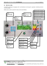
Page 4: ...t all of the main controls and indicators SW3 Discharge current selector switches DL14 Yellow LED Ongoing programming DY1 Multifunctional LCD display 4 lines x 20 chars DL13 Green LED 95 Battery DL15...

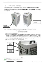
Page 5: ...ally pre set for a mains voltage range of 100 to 240V AC 50 60 Hz Make sure also to earth the discharger properly CONNECTION SEQUENCE 1 Connect the power cord to mains 2 Connect the battery to the soc...

Page 6: ...et to 5 h 00 minutes 3 Set the number of test cycles Cycl No to 3 A sequence of 3 discharges and 3 recharges is performed If the number is set to 0 only is a single discharge performed 4 Set the STOP...

Page 7: ...on to the right C resets ongoing failure indications which are not active any longer decreases a selected value OK confirms and saves a selected value then moves cursor forward SET enables special fun...

Page 8: ...1 EASY FW of V1 32 The parameters values can be varied using the control panel keys In particular Esc key exits programming and returns to START window key increases the selected value key recalls th...

Page 9: ...ttings THE HIGHLIGHTED FIELDS CANNOT BE MODIFIED MODOC DESCRIZIONE ISCAR A TS h m VST V el TCmin h m TCmax h m TPCar h m TPScar h m TEST Test liberi Ahnom 5 5 00 1 70 3 00 24 00 1 00 0 30 CICLI Cicli...

Page 10: ...FFICIENCY parameter is then calculated as follows EFFICIENCY DIS Ah 100 RatAh Charge stage charged capacity CH Ah is checked throughout every cycle When the minimum charge time i e MinCT is reached if...

Page 11: ...STV Mode Operation without charge cycles VCOST No 0 Only the ConstV constant voltage discharge phase is activated The Di selector switch can select the discharge limit current directly Positioning it...

Page 12: ...The selected interval appears on the final diagram A typical sampling interval of 5 minutes covers a period of 17 days altogether This data can be monitored by using the BLTView software for Windows o...

Page 13: ...PDTpphqqm TCTuuhvvm Where ttttt number of tests performed 1 to 99999 nn number of a specific cycle within the test 0 to 99 gg mm aa hh mm cycle start date and time Discharge data ffhggm Discharge time...

Page 14: ...ere nn Active fault warning window 1 to 15 Window no 1 always shows the most recent faults cc Active fault code description Active fault description The keys on the control panel feature following fun...

Page 15: ...connection Check protocol Contact service 7 ERROR ON 232 COM System Yes No Faulty communication on RS232 connection Check protocol Contact service 8 ERROR ON USB COM System Yes No Faulty communication...

Page 16: ...28 STOP V IN DISCH Discharge No Yes Battery voltage STV Recharge battery 29 REVERS BAT POLES Discharge Yes Yes Reversed connection of battery poles Reverse the battery pole connection 30 MOS CURRENT...

Page 17: ...A Power supply Vin 100 240 Vac 50 60 Hz I in 5A Vout 100 240 Vac 50 60 Hz I out 1A Environmental temperature 10 to 40 C Weight 56 Kg Equipped with a blue Anderson battery connector SBE 320 Equipped wi...

Page 18: ...ntage calibration Cal 0V Percentage correction of read value 0V Cal 5V Percentage correction of read value 5V Cal 20mA Percentage correction of read value 20mA CH Ah Charged Amperehours ChaI Charge cu...

Page 19: ...utes P_DIS Pause after discharging PDT Programmed discharge time in hours and minutes PRGDC Programmed discharge current PROG1 Display of programming page no 1 PROG2 Display of programming page no 2 P...

Page 20: ...11 P B M S r l via Barella Z I VIGNOLA MO ITALIA Tel 39 059 770 53 11 Fax 39 059 770 53 00 http www gruppopbm it e mail pbm gruppopbm it MU001033GJ_BLT160_GB_JAP rev5_190711 doc P 20 BLT160 BLT160 AP2...

Page 21: ...Barella Z I VIGNOLA MO ITALIA Tel 39 059 770 53 11 Fax 39 059 770 53 00 http www gruppopbm it e mail pbm gruppopbm it MU001033GJ_BLT160_GB_JAP rev5_190711 doc P 21 A BLT160 BLT160 a b BLT160 BLT160 BL...

Page 22: ...770 53 11 Fax 39 059 770 53 00 http www gruppopbm it e mail pbm gruppopbm it MU001033GJ_BLT160_GB_JAP rev5_190711 doc P 22 B BLT160 SW3 DL14 LED DY1 LCD 4 x 20 DL13 LED 95 DL15 LED 80 DL16 LED 60 DL18...

Page 23: ...1 P B M S r l via Barella Z I VIGNOLA MO ITALIA Tel 39 059 770 53 11 Fax 39 059 770 53 00 http www gruppopbm it e mail pbm gruppopbm it MU001033GJ_BLT160_GB_JAP rev5_190711 doc P 23 C AC BLT160 100 24...

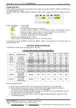
Page 24: ...0 53 00 http www gruppopbm it e mail pbm gruppopbm it MU001033GJ_BLT160_GB_JAP rev5_190711 doc P 24 LED 0 3 START 1 4V LED NOTE START PRG 1 SW4 AUTO RatV 2 SW3 10 160A DiscI Ahs RatAh DiscI 5 DT 5 00...

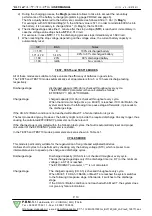
Page 25: ...770 53 00 http www gruppopbm it e mail pbm gruppopbm it MU001033GJ_BLT160_GB_JAP rev5_190711 doc P 25 D START 4x20 12 16 mm Is RatV Esc PRG PROG C OK SET InfoCar InfoScar START PRG PROG1 gg mm aa hh m...

Page 26: ...GJ_BLT160_GB_JAP rev5_190711 doc P 26 OK Esc PROG1 PRG PROG 2 MaxCT MinCT Mag PTaC PTaD StD PRG PROG3 gg mm aa hh mm b b 16 n n 32 PRG PROG4 TIPO B x aaaa PROG4 MODO PROG y bbbbbbb x aaaa 0 1 V1 31 y...

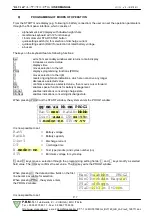
Page 27: ...3GJ_BLT160_GB_JAP rev5_190711 doc P 27 1 2 0V 1 2V in V el 0 6 0 1 Vnom 12 12 0 Volt VStop 1 70 1 02 V el Vgas 2 40 1 44 V el 1 EASY PROG2 PROG3 PROG4 MODO_TEST5 MODO_TEST10 PROG1 gg mm aa hh mm PROG1...

Page 28: ...h RatAh 5 5 00 1 70 3 00 24 00 1 00 0 30 TES10 10 h RatAh 10 10 00 1 70 3 00 24 00 1 00 0 30 C T5 N 1 RatAh 5 5 00 1 85 0 01 2 00 0 05 0 02 1 5 h RatAh 5 5 00 1 70 10 00 16 00 1 00 0 30 C T10 N 1 Rat...

Page 29: ...ww gruppopbm it e mail pbm gruppopbm it MU001033GJ_BLT160_GB_JAP rev5_190711 doc P 29 TEST TEST5 TEST10 TEST5 TEST10 5 10 DIS Ah EFFICIENCY EFFICIENCY DIS Ah 100 RatAh CH Ah MinCT CH Ah RatAh MaxCT CH...

Page 30: ...OLA MO ITALIA Tel 39 059 770 53 11 Fax 39 059 770 53 00 http www gruppopbm it e mail pbm gruppopbm it MU001033GJ_BLT160_GB_JAP rev5_190711 doc P 30 NC T5 NC T10 CYCLES TEST5 NC T5 TEST10 NC T10 0 ICOS...

Page 31: ...m it e mail pbm gruppopbm it MU001033GJ_BLT160_GB_JAP rev5_190711 doc P 31 Is ratAh ratAh AUTO AUTO BatV V ratV V BatV V ratV V 0 6 5 6 38 1 42 0 40 6 6 13 0 12 42 1 52 0 48 13 1 26 0 24 52 1 76 0 72...

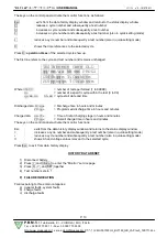
Page 32: ...il pbm gruppopbm it MU001033GJ_BLT160_GB_JAP rev5_190711 doc P 32 1 START CHARG P_CH DISCH P_DIS END 2 OLD TESTNttttt CNcc OLD DIS Ahaaaa AhC1Fbbbb EFF eee CH Ahcccc Vmin x xx VMax y yy ttttt 1 99999...

Page 33: ...IA Tel 39 059 770 53 11 Fax 39 059 770 53 00 http www gruppopbm it e mail pbm gruppopbm it MU001033GJ_BLT160_GB_JAP rev5_190711 doc P 33 ttttt 1 99999 nn 0 99 gg mm aa hh mm ffhggm Ffhggm sshttm Ffhgg...

Page 34: ...I VIGNOLA MO ITALIA Tel 39 059 770 53 11 Fax 39 059 770 53 00 http www gruppopbm it e mail pbm gruppopbm it MU001033GJ_BLT160_GB_JAP rev5_190711 doc P 34 SYSTEM FAULT Pnn cc fault descrip 1 cc fault...

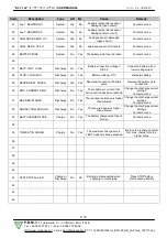
Page 35: ...ev5_190711 doc P 35 AR C BL AR BL 1 DEFECTIVE EEPROM 2 DEFECTIVE RTC 3 DEF INT THERMO 4 RTC BATTERY DOWN 5 RS485 POWER MISS RS485 6 ERROR ON 485 COM RS485 7 ERROR ON 232 COM RS232 8 ERROR ON USB COM U...

Page 36: ...BLT160_GB_JAP rev5_190711 doc P 36 AR BL 18 BATT T SENSOR CC 19 DISS T SENSOR OC 20 DISS T SENSOR SC 21 Aux T SENSOR OC 22 Aux T SENSOR SC 23 ANALOGUE SENS OC 24 ANAL SENS AT FS 25 BATTERY FUSE 26 27...

Page 37: ...w gruppopbm it e mail pbm gruppopbm it MU001033GJ_BLT160_GB_JAP rev5_190711 doc P 37 AR BL 40 41 TEST STOP due toB STOP 42 43 44 G 4V 96 V 2V 80A 160A 1 160A 100 240V 50 60 Hz 5A 100 240V 50 60 Hz 1A...

Page 38: ...pbm it e mail pbm gruppopbm it MU001033GJ_BLT160_GB_JAP rev5_190711 doc P 38 actN AhC1F ALARM An I An V Aux T Bah BatV C C T5 CYCLES TEST5 C T10 CYCLES TEST10 CableRes mOhm Cal Cal 0V 0V Cal 5V 5V Cal...

Page 39: ...001033GJ_BLT160_GB_JAP rev5_190711 doc P 39 K1 K1 ON OFF K2 K2 ON OFF K3 K3 ON OFF K4 K4 ON OFF K5 K5 ON OFF KB ON OFF Mag maxCT minCT maxV minV MosT Mosfet MosV Mosfet OLD P_CH PCT P_DIS PDT PRGDC PR...

Reviews: