MDT Construction Manual – Issue 2
Page 42
13.3
T
RANSMITTING
Do not transmit without a matched 40M antenna or 50 dummy load connected.
To transmit press the PTT button on your microphone and talk. The LED on the front panel will
flash as you speak. This provides an indication of the power output, as the current through the
LED, and therefore its brightness, is dependent on the peak RF output. If the LED is illuminated
at a constant level when talking, it indicates that you are driving the transmitter too hard and
causing clipping of the RF signal.
Overdriving will create distortion and excessive harmonic generation and must be
avoided.
To check your signal you can either, connect the MDT to a dummy load and monitor yourself
with headphones on a nearby receiver, or have a friend that lives close by listen to your signal.
The idea is to increase the Mic gain progressively while the receiving station sweeps across your
transmission looking for distortion and unwanted spurious byproducts. Set the Mic gain control
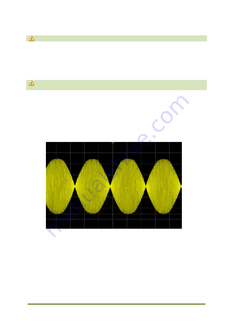
just below the point where these are noticeable. A screenshot from an oscilloscope placed
across a dummy load to monitor the output waveform is shown in Figure 23. The audio input to
the MDT mic socket was a 1KHz sine wave.
Figure 23 DSB transmit waveform
Congratulations your new DSB QRP transceiver is ready to put on the air.
Place the lid on the case, do up the two screws and have fun!
Summary of Contents for MDT
Page 1: ...MDT Construction Manual Issue 2 Page 1 MDT DSB TRANSCEIVER CONSTRUCTION MANUAL ...
Page 8: ...MDT Construction Manual Issue 2 Page 8 5 MDT BLOCK DIAGRAM Figure 3 MDT Block diagram ...
Page 12: ...MDT Construction Manual Issue 2 Page 12 Figure 4 Carrier oscillator ...
Page 13: ...MDT Construction Manual Issue 2 Page 13 Figure 5 Mixer ...
Page 14: ...MDT Construction Manual Issue 2 Page 14 Figure 6 Microphone Amplifier ...
Page 15: ...MDT Construction Manual Issue 2 Page 15 Figure 7 Transmit ...
Page 16: ...MDT Construction Manual Issue 2 Page 16 Figure 8 Receive Audio ...
Page 32: ...MDT Construction Manual Issue 2 Page 32 Figure 20 Component overlay ...


