MDT Construction Manual – Issue 2
Page 27
Step 14: LED
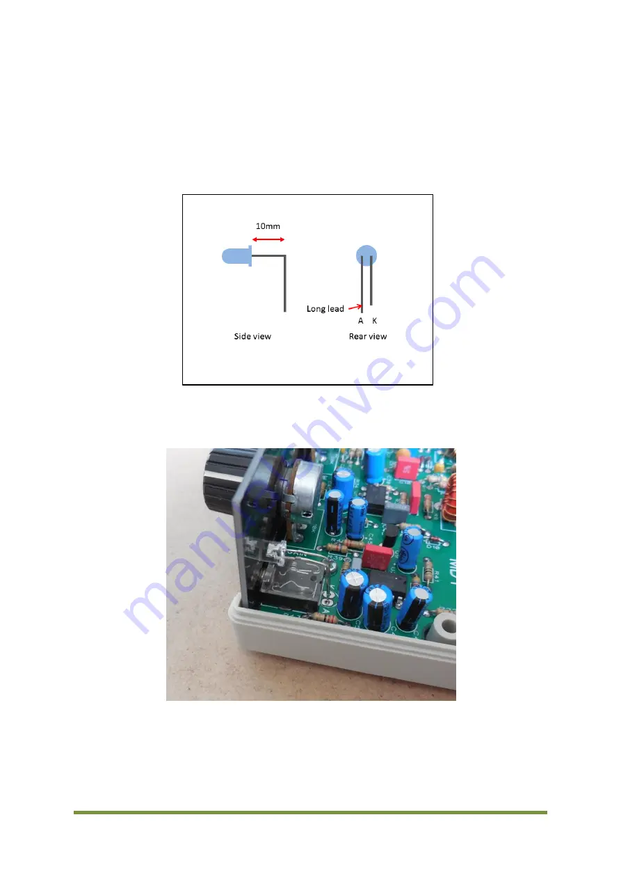
The LED leads need to be bent so that it can pass through the hole in the front panel. Figure 17
shows how this done. Once bent insert the LED leads into the PCB just far enough to allow them
to be soldered. Ensure the anode(A) and cathode(K) leads go in the correct holes as shown in
Figure 18.
Figure 17 LED lead bending
Figure 18 LED install
Summary of Contents for MDT
Page 1: ...MDT Construction Manual Issue 2 Page 1 MDT DSB TRANSCEIVER CONSTRUCTION MANUAL ...
Page 8: ...MDT Construction Manual Issue 2 Page 8 5 MDT BLOCK DIAGRAM Figure 3 MDT Block diagram ...
Page 12: ...MDT Construction Manual Issue 2 Page 12 Figure 4 Carrier oscillator ...
Page 13: ...MDT Construction Manual Issue 2 Page 13 Figure 5 Mixer ...
Page 14: ...MDT Construction Manual Issue 2 Page 14 Figure 6 Microphone Amplifier ...
Page 15: ...MDT Construction Manual Issue 2 Page 15 Figure 7 Transmit ...
Page 16: ...MDT Construction Manual Issue 2 Page 16 Figure 8 Receive Audio ...
Page 32: ...MDT Construction Manual Issue 2 Page 32 Figure 20 Component overlay ...


