


5. TROUBLESHOOTING
MAINTENANCE
Symptom
Possible
Cause
Suggested Solution
Mitre saw will
not start.
No power at
power point.
Check that the power switch is
on.
Cord not
connected.
Check that the cord is plugged
in.
Mitre saw
operates
sporadically or
at low power.
Low power supply
or improper
extension cord.
Inspect power supply or power
cords.
Worn or cracked
carbon brushes.
Inspect carbon brushes; replace
if damaged or worn.
Wood burns at
ends of cut
Dirty blade.
Clean blade using blade cleaner
or mineral spirits.
Material is
binding.
Check position of workpiece on
table. Material must be flat, flush
against fence & supported on
ends.
Workpiece
frays or chips
out.
Finished side is
down.
Keep finished side of workpiece
up or facing operator.
Blade chipped or
dull.
Check for damaged teeth.
Sharpen or replace blade.
Blade
inappropriate for
material.
Check blade manufacturer’s
recommendations for material
being cut. For cross cutting
hardwood & for precision cuts,
use a thin kerf blade with 60 or
more teeth.
Workpiece is
unsupported.
Use a thin piece of scrap
material, such as 6mm plywood
underneath or behind the
workpiece to support the edges
of the workpiece as it is being
cut.
Blade binds,
slowing or
stopping the
saw.
Workpiece is
misaligned or
the ends are not
supported.
Workpiece must be flat on
table, flush against the fence &
supported on both ends.
Workpiece is wet,
contaminated
or inappropriate
blade is being
used.
Check condition of workpiece &
check compatibility of blade to
workpiece.
Blade does not
cut completely
through
workpiece.
Depth stop
setting in use.
Move depth stop to right to
disengage.
Depth stop set
too shallow.
Adjust depth stop bolt for desired
depth of cut.
Changing The Blade
WARNING!
NEVER TRY TO USE A BLADE THAT IS
LARGER THAN THE STATED CAPACITY OF THE
MITRE SAW. IT MIGHT COME INTO CONTACT WITH
THE BLADE GUARD & RISK PERSONAL INJURY OR
DAMAGE TO THE MITRE SAW. THIS WILL NOT BE
COVERED UINDER WARRANTY.
WARNING!
NEVER USE A BLADE THAT IS TOO
THICK TO ALLOW THE OUTER BLADE WASHER
TO ENGAGE WITH THE FLATS ON THE SPINDLE,
IT WILL PREVENT THE BLADE SCREW FROM
PROPERLY SECURING THE BLADE ONTO THE
SPINDLE.
WARNING!
WEAR GLOVES WHEN PERFORMING A
BLADE CHANGE OPERATION.
1. Ensure the plug is disconnected from the mains
power supply. Ensure the cutting head is raised.
If the head lock down pin is locked in place, pull
the head lock down pin and gently raise the
cutting head.
2. Raise the lower guard out of the way and hold it
3. Using the 5mm Hex Key loosen the guard cover
screw until it disengages the blade bolt cover.
4. Swing the blade bolt cover up and out of the way
to reveal the bolt head in the centre of the blade.
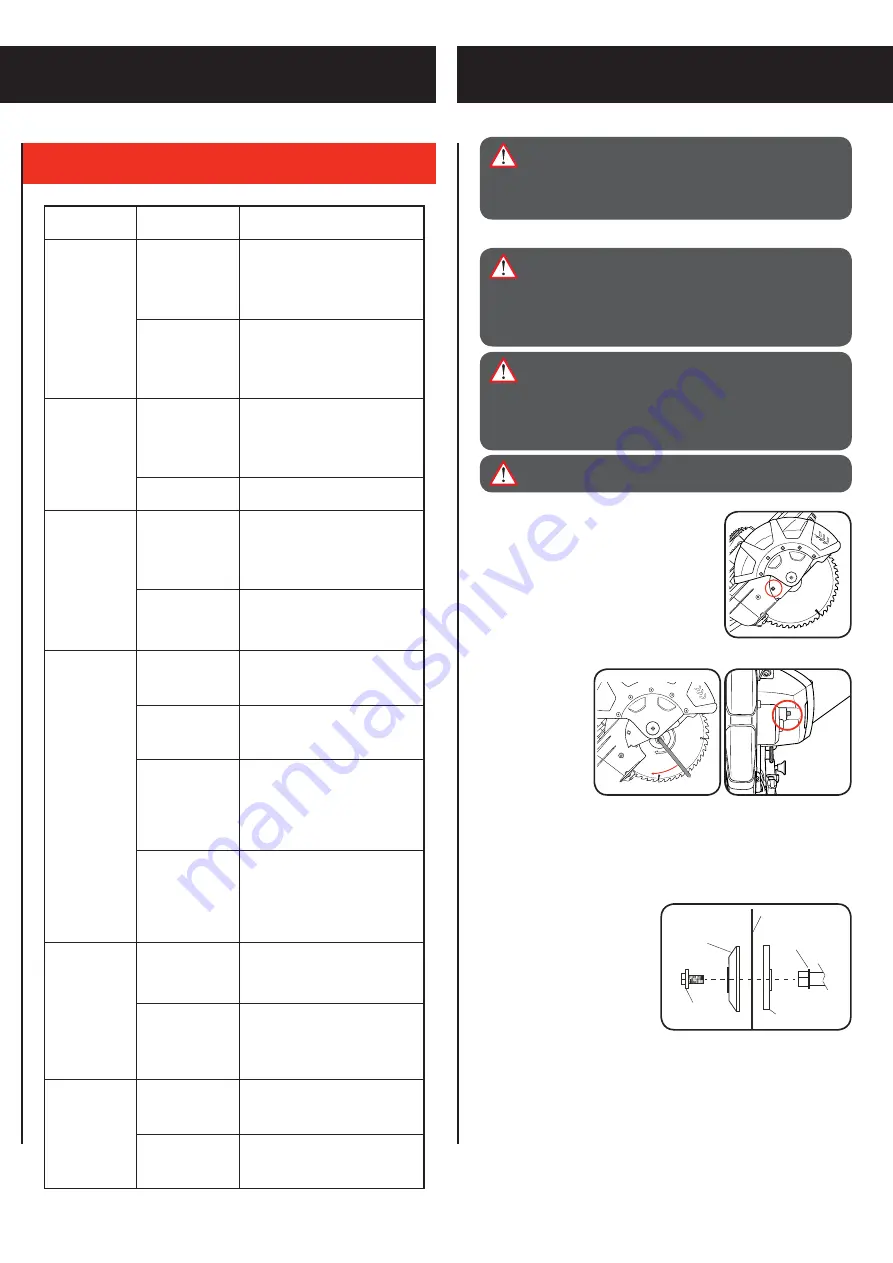
5. Place the 6mm Hex
Key onto the blade
bolt in the centre of
the blade.
6. Depress the spindle
lock button. To
ensure it engages
correctly, rotate the
Hex Key until the
spindle lock clicks into position.
Note:
The spindle lock button holds the blade in place when using the 6mm
Hex Key to change the blade.
7. Loosen the bolt in the centre of the blade by turning the Hex Key clockwise
as the blade bolt is a left hand thread.
Note:
Make sure the inner flange stays in place on the spindle.
8. Remove the blade bolt followed
by the outer flange. The blade can
now be removed by pulling away
from the spindle. Put it aside ready
to use in the reassembly of the
new blade.
Note:
Use a rubber mallet to tap the
blade off if it is stuck on the tool.
9. Install the new blade over the
spindle and onto the inner flange.
10. Replace the outer flange by placing the cupped side of the flange against
the blade followed by the blade bolt.
11. Place the 6mm Hex Key provided onto the blade bolt in the centre of the
blade.
12. Depress the spindle lock button. To ensure it engages correctly, rotate the
Hex Key until the spindle lock clicks into position.
13. Tighten the blade bolt in the centre of the blade by turning the Hex Key ant-
clockwise as the blade bolt is a left hand thread.
14. Swing the blade bolt cover back into place and secure it with the guard
cover screw. Make sure the lower guard operates smoothly and properly
protects from the blade before using the saw.
WARNING!
BEFORE CLEANING THE TOOL OR
CARRYING OUT ANY MAINTENANCE PROCEDURE,
MAKE SURE THAT IT IS DISCONNECTED FROM
THE POWER SUPPLY TO PREVENT ACCIDENTAL
STARTING.
Blade Bolt
Inner Flange
Outer Flange
Blade
Spindle


