


The MIG welder is supplied with a 0.2kg coil of 0.8mm gasless
welding wire. Welding wire up to 5kg can be fitted to this welder
using the 5kg coil adaptor.
2. SHIELDED GAS WELDING SETUP
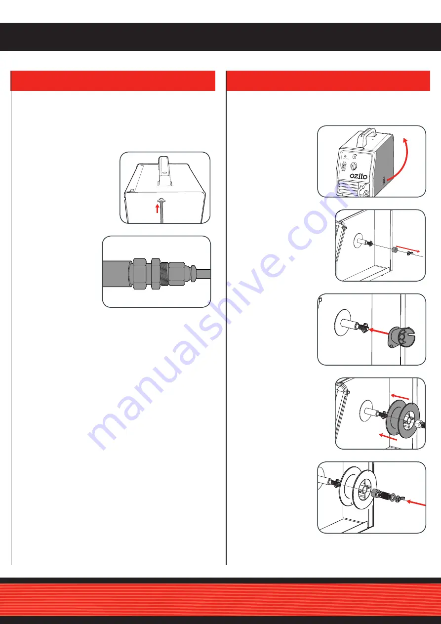
3. FITTING THE WELDING WIRE COIL
Attaching the Shielding Gas Hose and Regulator
1 Connect the hose to the
welder gas intake barb
and secure in place with
the appropriate hose
clamp.
2 Remove the wing nut by
rotating anti-clockwise and
remove the drive washer.
4 Slide the welding wire coil
onto the shaft.
When using a shielding gas with the MIG welder, you will
require additional hoses and gauges. These additional
accessories are available at your local gas supplier and are not
included with your MIG welder.
• Check with your local gas supplier for their recommendations
of the required gas mixture and flow rate for your MIG welder.
• Check all of the connections to the gauges and the shielding
gas bottle for leaks prior to commencing to weld.
2 When using a
shielding gas with
a disposable argon
gas bottle, you may
need to purchase
a hose reducing
adaptor from your
gas supplier.
3 If a 5kg wire coil is
to be fitted, slide the
coil adaptor onto
the wire drive shaft.
Note:
This step can
be skipped if a smaller
wire coil is to be fitted.
1 Open the side cover
by lifting the side
cover release lever.
5 Align the drive
washer lug with
the slot in the drive
shaft and secure
with the wing nut
but do not over
tighten.
0
16.2V
17.4V
18.5V
20V
OFF
ON
OVER-HEAT
Drive
washer (c)
Drive
shaft (a)
5.0kg Coil
adaptor (e)
0
16.2V
17.4V
18.5V
20V
OFF
ON
OVER-HEAT
0
16.2V
17.4V
18.5V
20V
OFF
ON
OVER-HEAT
Drive
washer (c)
Drive
shaft (a)
5.0kg Coil
adaptor (e)
0
16.2V
17.4V
18.5V
20V
OFF
ON
OVER-HEAT
Note:
Over tightening of the wing nut will restrict the wire feed
rate and can cause damage to the wire feed motor or irregular
welding.


