RT1003 Manual
Revision: 1
90628
101
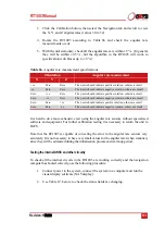
3. Click the Calibration button, then select the Navigation tab and scroll to view
the X, Y, and Z angular rates (values 30 to 32).
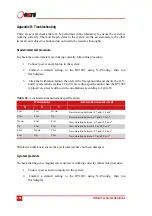
4. Rotate the RT1003 according to Table 66 and check the angular rate
measurements occur.
5. With the unit stationary, check all the angular rates are within ±5 °/s. (In general
they will be within ±0.5 °/s, but the algorithm in the RT1003 will work to
specification with biases up to ±5 °/s).
It is hard to do a more exhaustive test using the angular rate sensors without specialised
software and equipment. For further calibration testing it is necessary to return the unit to
OxTS.
Note that the RT1003 is capable of correcting the error in the angular rate sensors very
accurately. It is not necessary to have very small values for the angular rates when stationary
since they will be estimated during the initialisation process and warm-up period.
Testing the internal GNSS and other circuitry
To check all the internal circuits in the RT1003 are working correctly and the navigation
computer has booted correctly, use the following procedure:
1. Connect power to the system, connect the system to a computer and run the
visual display software (NAVdisplay).
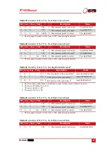
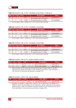
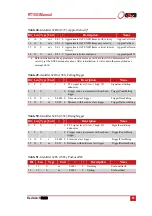
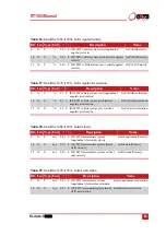
2. Use Table 67, below, to check the status fields are changing.
Table 66.
Angular rate measurement specifications
Orientation
Angular rate measurement
X
Y
Z
+ve
Zero
Zero
The x-axis should indicate positive rotation, others are small
-ve
Zero
Zero
The x-axis should indicate negative rotation, others are small.
Zero
+ve
Zero
The y-axis should indicate positive rotation, others are small
Zero
-ve
Zero
The y-axis should indicate negative rotation, others are small
Zero
Zero
+ve
The z-axis should indicate positive rotation, others are small
Zero
Zero
-ve
The z-axis should indicate negative rotation, others are small

