background image


2. Set the network parameters of the oscilloscope 


(1) 

Connect via USB and enter the menu

: Use the supplied USB cable to connect the oscilloscope with a PC through their USB ports


After connecting successfully, click   

  to show Function menu, choose "

Utility

", click "Network".   

 
(2) 

Set the network parameters of the oscilloscope: 

In Network menu, click "OK" to enter MachineNetSetting.   

Choose the oscilloscope to be connected from the list. If it's not in the list, click "Refresh" to refresh the list.   
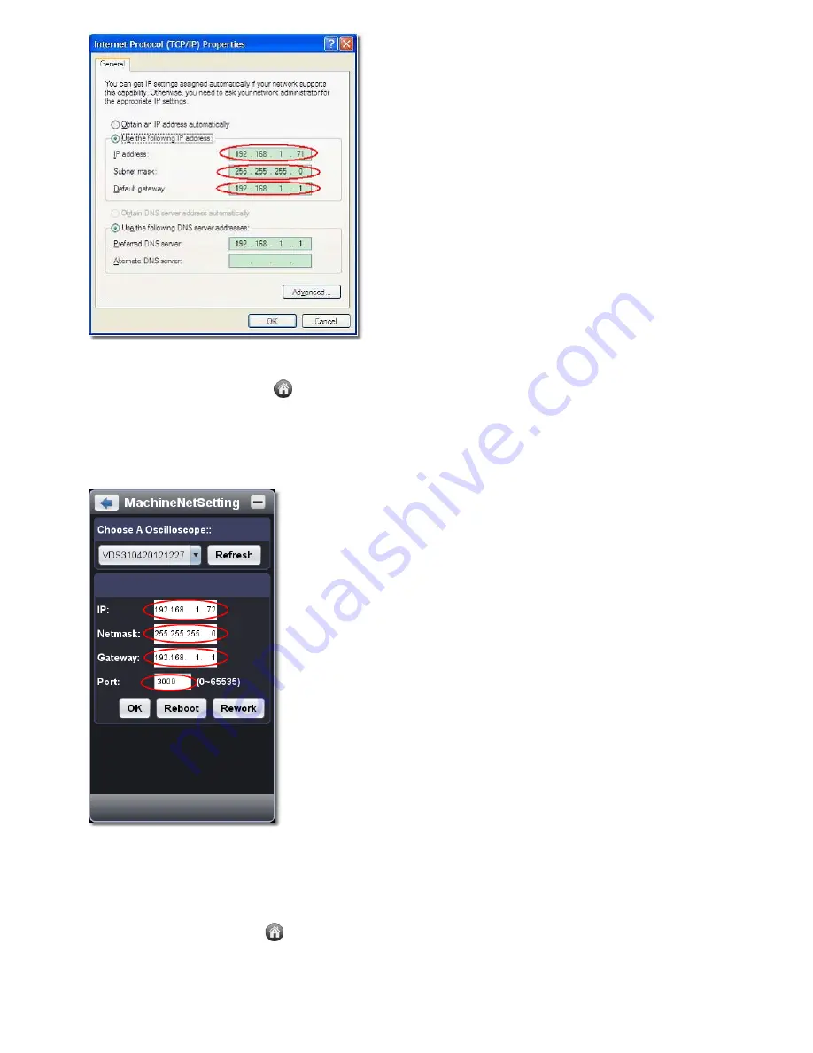
Set IP, the first three bytes should be same as the IP address of the computer in step 1, the last byte should be different. Here, we set it to 
192.168.1.72. The range of the port value is 0

4000, here we set it to 3000.   

The Net mask and Gateway should be set according to the router. 


(3)  Click "Rework" to restart the oscilloscope. 


3. Set the network parameters of the software


(1) 

Supply power

: Disconnect the USB cable from the computer. Connect it with the AC-DC adapter. Plug the adapter into an electrical 

outlet to power the oscilloscope.   

 
(2) 

Connect to the router

: Use a LAN cable to connect the oscilloscope with a router; the computer should be connected to the router too.   

(3) 

Set parameters in menu

: Click   

  to show Function menu, choose "

Utility

", click "Network". Set 

IP

 and 

Port

 to the same value of the 

oscilloscope in step 2.   


31


Summary of Contents for VDS Series

Page 1: ...VDS Series PC Oscilloscopes User Manual WWW OWON COM HK ...

Page 2: ...owever OWON will continue to improve products and reserves the rights to changes specification at any time without notice OWON is the registered trademark of the Lilliput Company Headquarter Fujian Lilliput Optoelectronics Technology Co Ltd The mansion of optoelectronics 19 Heming Road Lantian industrial zone Zhangzhou Fujian China Tel 86 596 2130430 Fax 86 596 2109272 Web www owon com hk Mail Bus...

Page 3: ...e This warranty shall not apply to any defect failure or damage caused by improper use or improper or inadequate maintenance and care Lilliput shall not be obligated to furnish service under this warranty a to repair damage resulting from attempts by personnel other than Lilliput representatives to install repair or service the product b to repair damage resulting from improper use or connection t...

Page 4: ...to Set the Vertical System 12 3 How to Set the Horizontal System 12 4 How to Set the Trigger System 13 5 How to Set the Channels 15 6 How to Measure Automatically 15 7 How to Implement Sampling Setup 17 8 How to Measure with Cursors 17 9 How to Set the Display System 19 10 Use Mathematical Manipulation Function 21 11 How to zoom the waveform 23 12 How to do Pass Fail test 25 13 How to Record and P...

Page 5: ...ows XP 32 bit 64 bit Windows Vista 32 bit 64 bit Windows 7 32 bit 64 bit Ports USB2 0 USB1 1 Display Resolution 1024 x 768 Ports Introduction VDS1022 I VDS2052 I 1 3 4 5 2 Figure Ports of the Oscilloscope take VDS1022 for instance 1 USB port Supply power by PC USB or the adapter communicate with PC 2 Probe Compensation Measurement signal 5V 1KHz output 3 MULTI port EXT trigger input trigger output...

Page 6: ...nel 2 7 Signal input of Channel 1 VDS2064 VDS3104 Figure Ports of the Oscilloscope take VDS3104 for instance 1 Probe Compensation Measurement signal 3 3V 1KHz output 2 MULTI port EXT trigger input trigger output or Pass Fail output 3 LAN port optional Network port which can be used to connect with PC 4 USB port Supply power by PC USB or the adapter communicate with PC 5 Signal input of Channel 4 6...

Page 7: ... please assure that the device is running well and plugged into PC from USB Right click Computer you can find it on the desktop or in Start menu in the pop up menu click Manage and it will open a window named Computer Management as follow in the left side click Device Manager it will show a devices tree in the middle and then click the last one button Scan for hardware changes in tool bar as follo...

Page 8: ...y that is under the software setup folder named USBDRV and the contents inside are like these Or like this than you should use the USBDRV directory to indicate the inf file and to the sys or dll file you can indicate then in different directories like x86 ia64 or amd64 depending on the CPU but most of time just x86 and amd64 are enough 4 ...

Page 9: ...ep the system is installing driver software for you as follow In the course It for Windows XP x86 x64 Windows Vista x86 x64 Windows 7 x86 may open a window named Windows Security as below and just select Install this driver software anyway to continue 5 ...

Page 10: ...ll to continue And then continue installing And finish Now a successful installation window opens with information Windows has successfully updated your driver software Close the window have a look at the Computer Management window you will find a device under LibUSB Win32 Devices it should be like this 6 ...

Page 11: ...x64 Plug into the running well device to open Found New Hardware Wizard dialog Or you can right click My Computer and select Manage in the left area of opened Computer Management select Device Manager double click the item USB Device with in the middle area to open the Wizard In the Wizard select No not this time 7 ...

Page 12: ...t Search for the best driver in these locations then select Include this location in the search and indicate a directory location for USB driver which is named as USBDRV and under the directory where you installed the program at Then the installation is running 8 ...

Page 13: ...show installed in Device Management Now you can use the program and use if for USB communication If there is an early version of USB driver in your computer you could try running reinstall bat to fix the file is under the directory of USBDRV 9 ...

Page 14: ...actory settings see Default Shortcut icon of exporting waveform see Pause Export Switch Three View One View In the Three View display mode the left top is XY mode widow the right top is FFT window Show hide Function menu 16 Trigger window see 4 How to Set the Trigger System 17 Sample and Period window see 3 How to Set the Horizontal System 18 19 Channel window of CH2 and CH1 see 2 How to Set the V...

Page 15: ...c the settings III Operations Instruction Relevant operations of this software 1 How to Set the Probe Attenuation Coefficient The probe has several attenuation coefficients which will influence the vertical scale factor of the oscilloscope To change or check the probe attenuation coefficient in the menu of oscilloscope 1 Click to show Function menu choose Channel 2 Set Probe Rate to the proper val...

Page 16: ...ge division of Channel 2 decreases one level S The voltage division of Channel 2 increases one level Cymometer It is a 6 digit cymometer The cymometer can measure frequencies from 2Hz to the full bandwidth Only if the measured channel has triggering signal and in Edge mode it can measure frequency correctly In the Single trigger mode it is a one channel cymometer and it can only measure the freque...

Page 17: ...r You can also click in the right bottom window to show it Trigger Control The oscilloscope provides two trigger types single trigger and alternate trigger Single trigger Use a trigger level to capture stable waveforms in two channels simultaneously Alternate trigger Trigger on non synchronized signals The Single Trigger and Alternate Trigger menus are described respectively as follows Single trig...

Page 18: ...When Line Number is selected you can set the line number 3 Set Hold Off About the setting method refer to Edge Trigger Slope Trigger Choose Mode as Slope to set the oscilloscope as the positive negative slope trigger within the specified time 1 Select slope condition 2 Set slope time 3 Set the High level upper limit and Low level lower limit 4 Set Trig Mode and Hold Off About the setting method re...

Page 19: ...ft bottom See figure below To invert a waveform Waveform inverted the displayed signal is turned 180 degrees against the phase of the earth potential Click to choose CH1 or CH2 check Opposite to invert the waveform uncheck it to display normally To set channel coupling DC Pass both AC and DC components of the input signal AC Block the DC component of the input signal Ground Disconnect the input si...

Page 20: ... the entire waveform Vmin The minimum amplitude The most negative peak voltage measured over the entire waveform Vamp Voltage between Vtop and Vbase of a waveform Vtop Voltage of the waveform s flat top useful for square pulse waveforms Vbase Voltage of the waveform s flat base useful for square pulse waveforms Overshoot Defined as Vmax Vtop Vamp useful for square and pulse waveforms Preshoot Defi...

Page 21: ...g burr and the possibility of reducing the confusion Average It is used to reduce the random and don t care noises with the editable number 1 number 128 of averages Figure Normal sampling mode display in which no burr can be detected Figure Peak Detect mode under which the burrs on the falling edge of the square wave can be detected and the noise is heavy Figure The displayed waveform after the no...

Page 22: ... and Cursor 2 according to the waveform to be measured The cursor increment window at the left bottom shows current time of the two cursors absolute time difference of the two cursors and frequency See figure below Voltage cursor measurement Tick on Voltage option then two light red lines which represent Cursor 1 and Cursor 2 display along the horizontal direction Place the mouse pointer over Curs...

Page 23: ...on the bottom left of FFT window shows current frequency of the two cursors absolute frequency difference of the two cursors See figure below Vamp Measurement Tick on Amplitude enter Home page Math FFT then two light red lines represent Cursor 1 and Cursor 2 show along the horizontal direction on FFT window Place the mouse cursor on Cursor 1 or Cursor 2 drag after the mouse shape changing to adjus...

Page 24: ...ode Choose the first channel and the second channel In XY mode widow the first channel is displayed in the horizontal axis and the second in the vertical axis Note XY Mode only support 1K storage memory The storage memory is set to 1K automatically Persistence When the Persistence function is used the persistence display effect of the picture tube oscilloscope can be simulated The reserved origina...

Page 25: ...sion of M The software transforms the waveform data of the two factors into selected voltage division of M and calculates The green calculated waveform M is displayed in the screen Using FFT function The FFT fast Fourier transform math function mathematically converts a time domain waveform into its frequency components It is very useful for analyzing the input signal on Oscilloscope You can match...

Page 26: ...e Best type for measuring the frequency spectrum of non repetitive signals and measuring frequency components near DC Recommend to use for Transients or bursts the signal level before and after the event are nearly equal Equal amplitude sine waves with frequencies those are very close Broadband random noise with a relatively slow varying spectrum Blackman Best solution for magnitude worst for freq...

Page 27: ...itive or single shot events set the oscilloscope acquisition mode to average What is Nyquist frequency The Nyquist frequency is the highest frequency that any real time digitizing oscilloscope can acquire without aliasing This frequency is half of the sample rate Frequencies above the Nyquist frequency will be under sampled which causes aliasing So pay more attention to the relation between the fr...

Page 28: ...ust the horizontal position of the area in main window by it Note In Assist Set status the time base and horizontal trigger position can not be set Window Expansion Click Zoom the window area defined by two cursors will be expanded to the full screen size You can adjust the time base W and horizontal trigger position Tw of zoom window in the menu You can also drag the red pointer to adjust the hor...

Page 29: ... or pass signal by built in and configurable output port To run the test read the following steps 1 Choose channel Options include CH1 CH2 and Math 2 Set horizontal tolerance and vertical tolerance You can adjust by or input directly 3 Click Create Rule 4 Set output type Choose Pass or Fail Check or uncheck Ring Message Show and Stop Once as needed Ring The bell rings when it meets the rule Stop O...

Page 30: ...ord Record 1 Choose Record tab on the top 2 Click Preset Save Path to specify the save location Waveform files have the suffix cap 3 Set Interval Time and End Frame Interval Time refers to the interval between recorded frames Interval Time ranges from 0 to 100000ms and increment by 10ms 4 Make the waveform in Run status 5 Click Begin Record Counter starts to count the frame number 6 Click End Reco...

Page 31: ...ue for interface skin Then Restart button will appear After clicking it the software will be closed and restarted to apply the new skin Open File Choose BIN waveform file saved and open it or just drag the file into the software interface to open it Print Preview Click to open the Print Preview Window Instruction of the menu items in Print Preview Window File Page Set Set the page margins Print En...

Page 32: ...oscilloscope reach the optimum condition rapidly to obtain the most accurate measurement value You can carry out this application program at any time This program must be executed whenever the change of ambient temperature is 5 or over Before performing a self calibration disconnect all probes or wires from the input connector After everything is ready click Self Cal Default Click Default to call ...

Page 33: ...ard Shortcuts Enter Auto set Space Run Stop 16 Use LAN Port Using the LAN port the oscilloscope could be connected to a PC directly or through a router Below introduces these two kind of connection methods Connect directly via a LAN cable 1 View the network parameters of the computer View the IP address of the computer to connect to Assume the IP address is 192 168 1 71 2 Set the network parameter...

Page 34: ... other end into the LAN interface of the computer 3 Set parameters in menu Click to show Function menu choose Utility click Network Set IP and Port to the same value of the oscilloscope in step 2 4 Click Connect Connect through a router 1 View the network parameters of the computer View the network parameters of the computer to connect to The Default gateway and Subnet mask should be set according...

Page 35: ...the computer in step 1 the last byte should be different Here we set it to 192 168 1 72 The range of the port value is 0 4000 here we set it to 3000 The Net mask and Gateway should be set according to the router 3 Click Rework to restart the oscilloscope 3 Set the network parameters of the software 1 Supply power Disconnect the USB cable from the computer Connect it with the AC DC adapter Plug the...

Page 36: ...ility menu see Self Cal Note VDS1022 I represents two types of machines they are VDS1022I and VDS1022 VDS1022I contains isolation while VDS1022 does not contain isolation The same as VDS2052 I Performance Characteristics Instruction Bandwidth VDS1022 I 25MHz VDS2052 I 50MHz VDS2062 60MHz VDS3102 100MHz VDS2064 60MHz VDS3104 100MHz Channel VDS1022 I VDS2052 I VDS2062 VDS3102 2 1 External VDS2064 VD...

Page 37: ...MS s Single CH 0 5S s 100MS s VDS2052 I Dual CH 0 5S s 250MS s Single CH 0 5S s 250MS s VDS2062 Dual CH 0 5S s 250MS s Single CH 0 5S s 500MS s VDS3102 Dual CH 0 5S s 500MS s Single CH 0 5S s 1GS s VDS2064 Four CH 0 5S s 125MS s Dual CH 0 5S s 250MS s Single CH 0 5S s 500MS s VDS3104 Four CH 0 5S s 250MS s Dual CH 0 5S s 500MS s Single CH 0 5S s 1GS s Interpolation sin x x Max Record length VDS102...

Page 38: ...ity VDS1022 I VDS2052 I VDS2062 VDS2064 5mV div 5V div VDS3102 VDS3104 2mV div 5V div Displacement VDS1022 I 10div VDS2052 I 10div VDS2062 1V 5mV 100mV 50V 200mV 5V VDS3102 1V 2mV 100mV 50V 200mV 5V VDS2064 1V 5mV 100mV 50V 200mV 5V VDS3104 2V 2mV 200mV 50V 500mV 5V Analog bandwidth 25MHz 50MHz 60MHz 100MHz Single bandwidth Full bandwidth Low Frequency 10Hz at input AC coupling 3dB Rise time VDS10...

Page 39: ...s to trigger in trigger output or Pass Fail output Trigger Performance Characteristics Instruction Trigger level range Internal 5 div from the screen center Trigger level Accuracy typical Internal 0 3div EXT TTL Trigger displacement According to Record length and time base Trigger Holdoff range 100ns 10s 50 level setting typical Input signal frequency 50Hz Edge trigger slope Rising Falling Pulse t...

Page 40: ...2062 VDS3102 VDS2064 VDS3104 About 3 3V with the Peak to Peak voltage 1MΩ Frequency Typical Square wave of 1KHz Power Mains Voltage VDS1022 I VDS2052 I 5 0V 500mA VDS2062 L VDS3102 L VDS2064 VDS3104 5 0V 1A Power Consumption VDS1022 I VDS2052 I 2 5W VDS2062 L VDS3102 L VDS2064 VDS3104 5W Environment Temperature Working temperature 0 40 Storage temperature 20 60 Relative Humidity 90 Height Operatin...

Reviews: