


6.Communication with PC
39
Connect through a router
(1)
Connection
. Use a LAN cable to connect the Waveform Generator with a router, the
LAN port of the Waveform Generator is in the rear panel; the computer should be
connected to the router too.
(2)
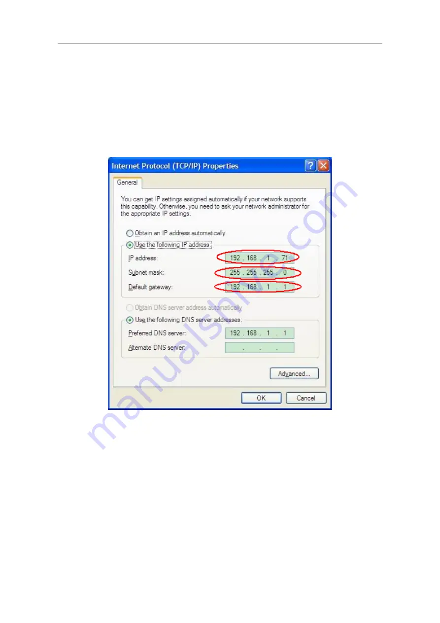
Set the network parameters of the computer
. Since the Waveform Generator can
not support obtaining an IP address automatically, you should assign a static IP
address. The Default gateway and Subnet mask should be set according to the router.
Here we set the IP address to 192.168.1.71, Subnet mask is 255.255.255.0, Default
gateway is 192.168.1.1.
Figure 6-3: Set the network parameters of the computer
(3)
Set the network parameters of the ultrawave software.
Run the software on the
computer; choose the "Ports-settings" of the "Communications" menu item. Set
"Connect using" to LAN. About the IP, the first three bytes is same as the IP in the
step (2), the last byte should be different. Here, we set it to 192.168.1.99. The range
of the port value is 0 - 4000, but the port which under 2000 is always be used, so it is
suggested to set it to the value above 2000. Here, we set it to 3000.


