4
4.2 Temperature setting
Suitable measures (e.g. safety valves) have to be taken to
ensure that the maximum and minimum operating tempera-
tures are not exceeded or undercut.
ap
pr
ox
.2
8°
C
ap
pr
ox
.2
4°
C
ap
pr
ox
.2
0°
C
ap
pr
ox
. 1
6°
C
ap
pr
ox
.1
2°
C
ap
pr
ox
. 7
°C
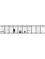
4.3 Dimensions
6. Installation / Removal
6.1 Installation
Do not fit the thermostat until all building work has been com-
pleted to avoid damage to the thermostat. Do not use excessive
force during thermostat installation to avoid damage to the ther-
mostat and the squeeze connection. The thermostat should be
installed by a specialist heating company.
If the single-lever thermostat is mounted in connection with a valve
and a radiator parallel to the wall, a minimum distance of 50 mm to
the wall has to be kept.
Illustr. 4.1 Dimensions
7. Maintenance
The thermostat is maintenance-free.
Only clean surfaces with a mild liquid detergent or soap suds.
Scouring agents, solvents and sharp cleaning agents may cause
damage to the surface and the imprint on the thermostat. The
thermostat must not be cleaned in a dish washer.
8. Disposal
To protect the sensor liquid from escaping, the thermostat
must not be destroyed when disposed of.
The thermostat contains hazardous waste!
Dismounted/defective thermostats can be returned to the
manufacturer Oventrop. Address see front page.
9. General terms and conditions of sale
and delivery
Oventrops general terms and conditions of sale and delivery
valid at the time of supply are applicable.
5. Function
Together with the mounted thermostat, the valve constitutes an
automatic temperature controller. The required room temperatu-
re is achieved by turning the handgrip of the thermostat to the
corresponding graduation figure. If the room temperature lies
below the set value at the thermostat, hot water enters the radia-
tor via the valve.
The heat is emitted to the room and the temperature rises until
the set value has been reached.
with collar nut cover
WARNING
!
NOTICE
ACHTUNG
1. Turn the handgrip (f) of the thermostat anticlockwise until the
figure “5” is in line with the indicator mark. Screw back collar
nut (e) completely (as illustrated).
2. Slip thermostat onto the valve body until stop (a). Turn
thermostat slightly to the left or right until the inner cams (c)
and grooves (b) click into position.
3. Firmly push thermostat towards the valve body (g) while firmly
tightening the collar nut (e) towards the collar (d).
4. Mount enclosed collar nut cover.
Now set the single-lever thermostat to the required room
temperature.
Observe warning advice under paragraph 2 (safety
notes)!
!
6.2 Removal
1. If required, remove the mounted collar nut cover with the help
of a suitable tool by pushing it into the allowance of the snap
connection (the tool must not be turned!).
2. Loosen the collar nut of the thermostat, screw it back
completely and remove the thermostat from the valve.
Ø 45
Ø 42
Ø
7
8
7
(
m
a
x
.
8
9
)
48