Eureka5 User Manual
CXD-
930
-UM-
044
Version: 1.3
Page
18
of
50
3.3
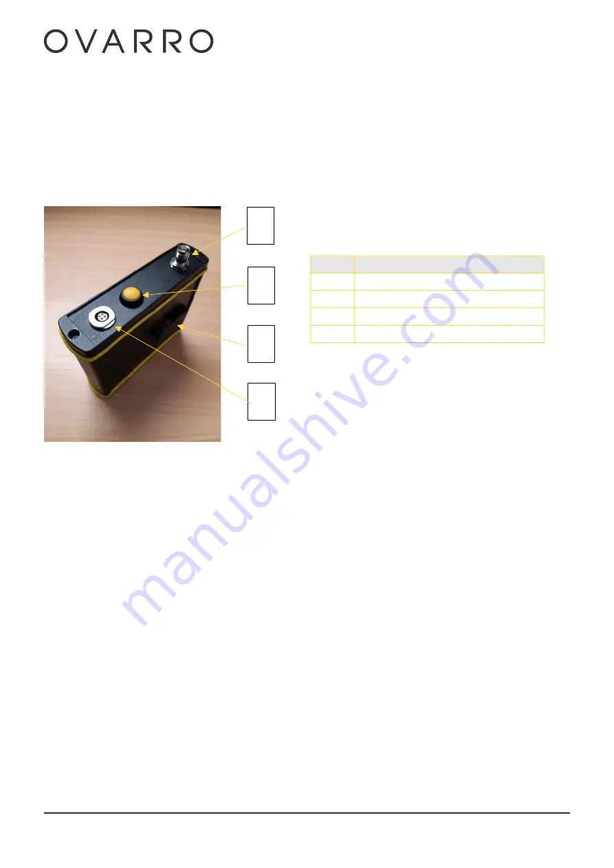
Receiver Unit
The Receiver Unit receives and processes the noise data from the radio transmitters and then transmits the data via Wi-
Fi
to
a Tablet running the
EUREKA GO
App
to produce a leak noise correlation
.
3.3.1
Antenna Socket
The antenna TNC socket allows the connection of one of the three supplied antenna that are stored in the transport case
.
3.3.2
On/Off Push Button Switch
The on/off push button switch (B in the photo) has several functions:
-
When the Receiver is off:
•
A single press of the button will start the power on process. At this point the Power LED will turn on. Approximately 90
seconds later the Wi-
Fi Status LED will start to flash fast and intermittently. The unit is not fully powered until the Wi
-
Fi
Status LED is flashing slowly & steadily. This indicates that the Wi
-
Fi is trying to connect to the tablet.
When the Receiver is on:
•
Two
quick presses of the button will start the power down process. The Wi
-
Fi Status LED will flash fast and steady
for a
few seconds and then
the Power LED will turn off. The unit is now powered down.
•
Pressing and holding the button
for longer than 6 seconds will cause a forced power
-
down and reset the unit. This
operation should be avoided as it can limit the life of the internal memory card.
Key
Description
A
Antenna Socket
B
On/Off Push Button Switch (Yellow)
C
Belt clip
D
Charge Input Socket
D
A
B
C
Summary of Contents for Eureka5
Page 1: ...Version 1 3 Eureka5 User Manual 24 March 2022 CXD 930 UM 044...
Page 6: ...Eureka5 User Manual CXD 930 UM 044 Version 1 3 Page 6 of 50 11 Appendix E EU DoC 49...
Page 11: ...Eureka5 User Manual CXD 930 UM 044 Version 1 3 Page 11 of 50...
Page 48: ...Eureka5 User Manual CXD 930 UM 044 Version 1 3 Page 48 of 50 10 Appendix D UKCA DoC TBA...
Page 49: ...Eureka5 User Manual CXD 930 UM 044 Version 1 3 Page 49 of 50 11 Appendix E EU DoC TBA...


