031-331-B1-001, Rev. A (11/2015)
031-331-B1-001, Rev. A (11/2015)
12
13
Wiring the System, Morningstar TriStar MPPT-30 Charge Controller
3
4
5
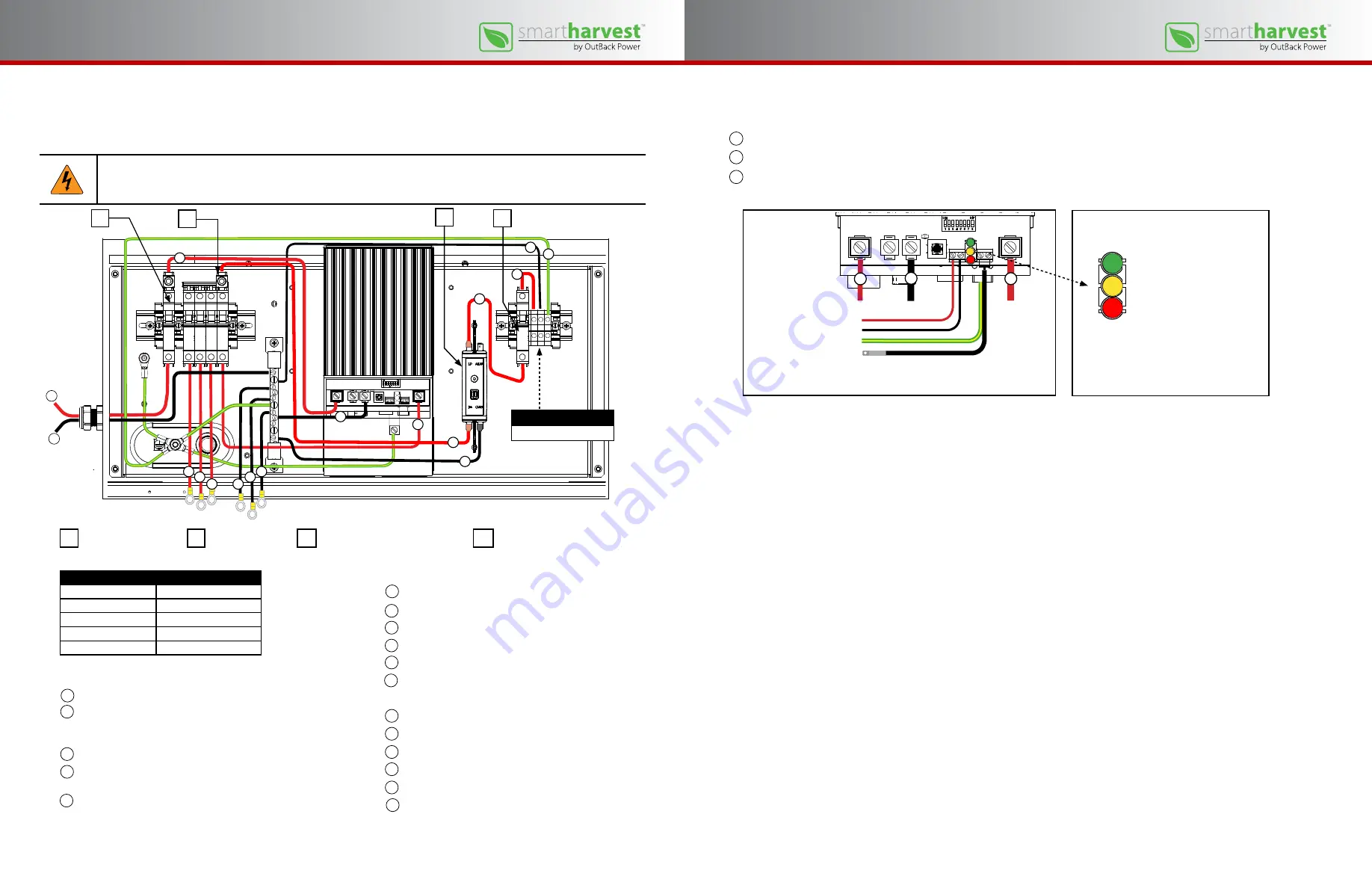
Connection detail, charge controller termination board
PV module positive (+) to the charge controller PV positive (+)
Battery positive (+) from the charge controller to the master DC circuit breaker
Battery negative (–) from the charge controller to the negative bus bar
Charge Controller connections, LEDs, battery sense wiring and remote
temperature sensor wiring
Battery temperature sensor
Battery sense positive (+)
Battery sense negative (–)
3
4
5
To enclosure ground
Illustrations courtesy of Morningstar Corp.
LED indicators
Three LED indicators provide information
regarding general controller transitions, battery
status, controller faults and alarms.
Green
Yellow
Red
A
B
C
D
6
Wiring the System, Morningstar TriStar MPPT-30 Charge Controller
Circuit Breaker Specifications
Wire Size mm
2
(IEC)
0.75 to 35 mm
2
Wire Gauge (UL)
18 to 2 AWG
Torque (IEC)
2.5 Nm
Torque (UL)
20 in-lb
Comments
Pozidriv #2 Combi head
7
8
9
10
11
12
13
14
15
Battery string connections
String #1 positive (+)
String #2 positive (+)
String #3 positive (+)
String #1 negative (–)
String #2 negative (–)
String #3 negative (–)
Load connections
Battery bus to LVD positive (+)
LVD negative (–) to negative bus bar
LVD (Load) to Load output circuit breaker
DC output voltage positive (+)
DC output voltage negative (–)
Ground connection (–)
Teminal block wiring torque value = 0.9 Nm / 8 in-lb
PV module connections
PV module positive (+)
PV module negative (–)
Charge Controller connections
PV module positive (+) to charge controller PV positive (+)
Battery positive (+) from charge controller to DC bus master
circuit breaker
Battery negative (–) from charge controller to negative bus bar
1
2
3
4
5
A
PV module breaker
B
DC bus breaker
C
Low voltage disconnect (LVD)
D
Load output breaker
WARNING: Electrical hazard
Only qualified personnel should install and wire the system or have access to the inside of the enclosure.
The system is shipped with the bulk of the wiring connections already in place. Use a #2 Phillips screwdriver to remove the four
(4) screws that secure the wiring box cover. Verify the pre-existing wiring is still in place and tightened to proper torque settings.
Replace the cover after inspecting the connections.
6
7
4
3
1
2
12
5
9
11
10
8
13
14
16
Illustration of Morningstar TriStar MPPT-30 Charge Controller courtesy of Morningstar Corp.
17
15
Terminal block torque
0.9 Nm / 8 in-lb
16
17


