OutBack reserves the right to make changes to the products and information contained in this document without notice.
Copyright © 2015 OutBack Power. All Rights Reserved. OutBack
is a registered trademark of The Alpha Group. p/n 044-026-B0-001, Rev. A (03/2015)
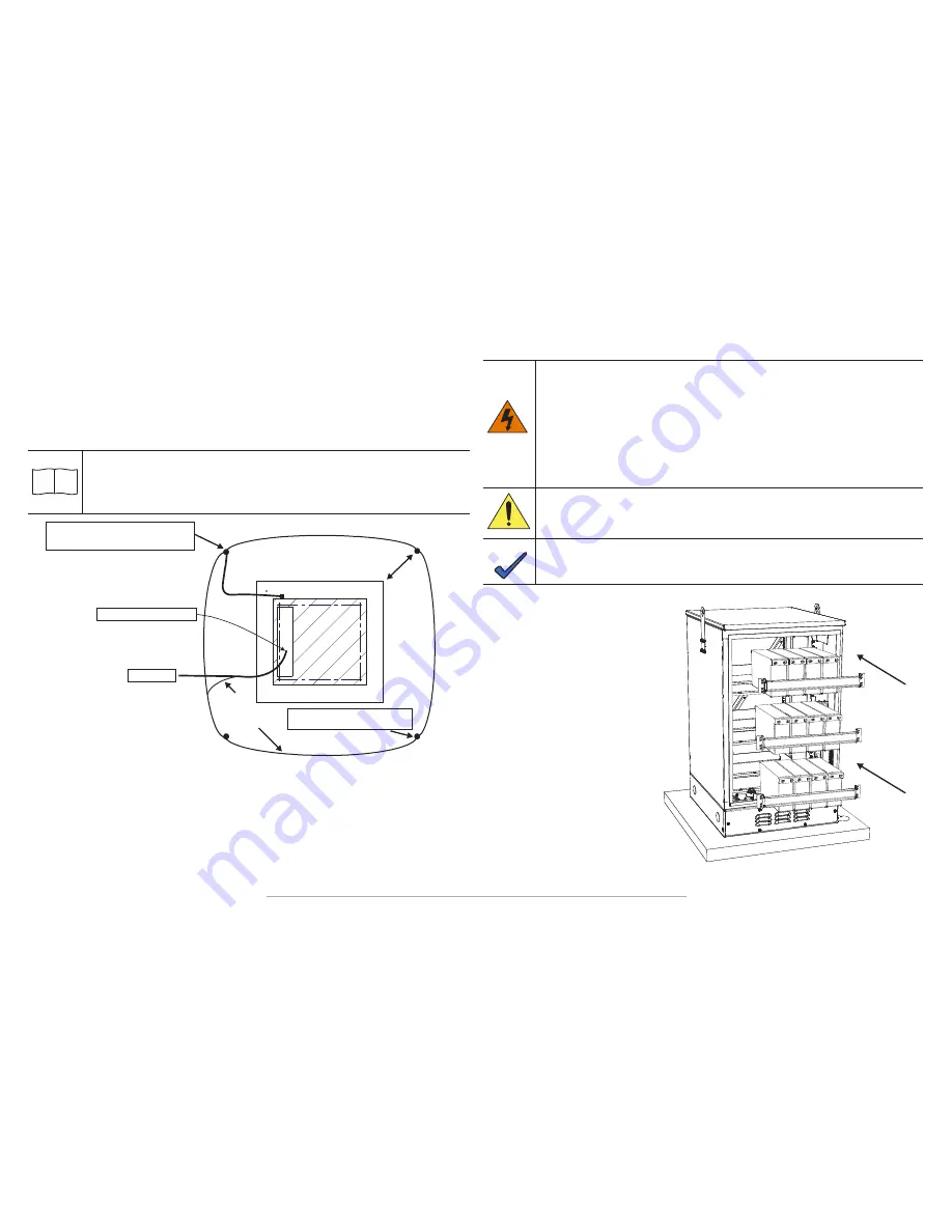
Battery Installation Procedure:
1. Remove the front door of the
enclosure by turning the two wing
knobs located on the door of the
enclosure.
2. Ensure ALL battery breakers are OFF.
3. On the top shelf of the enclosure,
remove the 8 screws on the securing
bar and set the securing bar aside.
4. Position the batteries as shown in
Figure 9.
5. Wire the batteries on the top shelf
using the busbars in accordance
with Figures 10 and 11, torquing
the connections to the battery
manufacturer's recommendation.
6. Using the negative battery cable,
wire the cable to the leftmost
negative battery terminal on the top
shelf of the enclosure .
Battery Installation
WARNING: Serious Personal Injury
Battery systems contain dangerous voltages. Observe the following precautions to reduce the risk
of electrical shock when maintaining batteries:
•
Ensure that all breakers are OFF.
•
Remove all personal metal objects (watches, rings, etc.).
•
Always use insulated tools.
•
Wear eye protection and rubber gloves.
•
Observe circuit polarities.
•
Do not make or break live circuits.
•
Never rest tools on top of batteries or other electrical parts.
Caution: Personal Injury
•
The front-terminal batteries weight approximately 115 lbs (52.2 kg). Use an appropriate lifting
device, or have two people lift the battery into the enclosure.
NOTE: Additional Equipment Information
•
Please review battery manual for best safety practices or consult your battery manufacturer
specifications for further safety information before installing batteries.
Figure 9, Battery Installation
Enclosure Grounding
Outback recommends 5 ohm minimum ground resistance between enclosure and ground rods, in accordance
with IEEE 1100-1999, Powering and Grounding Electronic Equipment.
Outback assumes no responsibility or liability for failure of the installer to comply with the requirements of
applicable local and national codes. Where allowed, exothermic welding may be used as an alternative to Burndy
clamps and connectors.
Grounding connections are located at the bottom of the enclosure, above the riser.
Outback recommends using the grounding method illustrated below. The grounding
method for a particular site will be dependent upon soil type, available space, local codes,
NEC (National Electric Code), and other site-specific characteristics.
INFORMATION:
i
Service Grounding (required)
1. #6 AWG bare copper wire from Service Neutral / Ground Bar.
Lightning Protection (optional)
2. 1/2" x 8' (1.3 cm x 2.4 m) copper ground rod, four places, driven about 2' (0.6 m) (typical) from the corners of
the pad.
3. #6 AWG bare copper wire loop terminated to each ground rod and buried below grade 30" (76 cm) (min)
4. Corrosion-proof connections (25+ year life-span), and hardware suitable for direct burial MUST be used.
5. #6 AWG bare copper wire from the loop to the enclosure.
Figure 8, Suggested Enclosure Grounding
Enclosure Footprint
2 f
eet
#2 AWG
#6 AWG
min
Connection made with Burndy Connector
(P/N YGHP58C2W-2TN or equivalent)
Enclosure Ground Loop
Connection made with Burndy Connector
(P/N YGHR58C2W-3 or equivalent)
Terminate at Enclosure Ground
Service Ground


