background image

1

1

2

2

3

3

4

4

5

5

6

6

7

7

8

8

A

A

B

B

C

C

D

D

SHEET

 1  

OF

 1 

DRAWN

CHECKED

QA

MFG

APPROVED

Henri

10/1/2016

DWG NO

assy_11

TITLE

SIZE

D

SCALE

REV

1 : 1

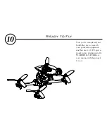
Now you’ve completed your 
build. Be sure to research 
your particular equipment 
and be sure it is 100% opera-
tional before attempting to fly. 
WARNING: NEVER test 
your motors with the propel-
lers on. 

10

Ready to Fly

Summary of Contents for VLS230

Page 1: ...5 6 7 8 A B C VLS230Assembly manual Patent Pending V1 020170723 ...

Page 2: ...ere are fine points covered that you will miss if you only assemble by the pictures You will enjoy your journey much more if you follow the instructions provided in this manual As always we are dedicated to your drone flying experience and if you have thoughts suggestions concerns or want to share a happy flight please feel free to contact us ootbinnovations gmail com DISCLAIMER Out of the Box Inn...

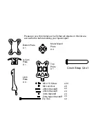
Page 3: ...2 M3x16 M3x20 34 5 6 7 8 A B C D 14 15 20 25 28 40 5 1 5 75 8 6 4 3 3 2 M2x20 M2x6 M2x10 M3x6 M3x6 M3x8 M3x10 M3x10 M3x10 M3x12 M3x16 M3x20 34 4 5 6 7 8 B C D 14 15 20 25 28 40 5 1 5 75 8 6 4 3 3 2 M2x20 M2x6 M2x10 M3x6 M3x6 M3x8 M3x10 M3x10 M3x10 M3x12 M3x16 M3x20 34 4 5 6 7 8 C D 14 15 20 25 28 40 5 1 5 75 8 6 4 3 3 2 M2x20 M2x6 M2x10 M3x6 M3x6 M3x8 M3x10 M3x10 M3x10 M3x12 M3x16 M3x20 34 5 6 7 8...

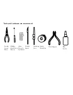
Page 4: ...Solder With Flux Wire Clippers Blue Loctite Tools and hardware we recommend Needle Nosed Pliers Phillips Head Screw Drivers Allen Wrench Set Metric Hobby Knife Soldering Iron Solder ...

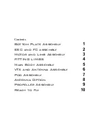
Page 5: ...ts Bottom Plate Assembly 1 ESC and FC assembly 2 Motor and Limb Assembly 3 FITTING LIMBS 4 Main Body Assembly 5 VTX and Antenna Assembly 6 Pod Assembly 7 Antenna Option 8 Propeller Assembly 9 Ready to Fly 10 ...

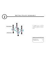
Page 6: ...What you need for this step Using M3 screws secure the 20mm standoff to the main plate M3 x 10 Screw 20 MM Standoff x 4 x 4 6 7 8 A B 20mm Standoff M3 x 10 Screw 1 Bottom Plate Assembly ...

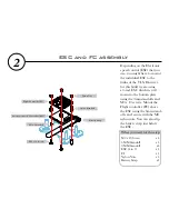
Page 7: ... 3mm standoffs and M3 x 10 screws Mount the Flight controller FC above the ESC using the 6mm stand offs and secure with the M3 nylon nuts You can also slip the battery strap just below the ESC M3 x 10 Screw 5 MM Standoff 3 MM Standoff ESC 4 in 1 FC Nylon Nuts Battery Strap x 4 x 4 x4 x 1 x 1 x 4 x1 6 7 8 A B C Flight Controller FC Electronic Speed Controller ESC 5mm Standoff Battery Strap Nylon Nu...

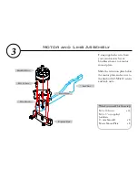
Page 8: ... mount plate Slide the retention plate below the motor plate and secure to the limb with 2 M3x10 screws and lock nuts M3 x 10 Screw M3 x 6 or supplied hardware 15 mm Standoff Motor Mount Plate x 16 x 8 x 8 3 Motor and Limb Assembly Brushless Motor M3 x 6 Screw M3 x 10 Screw Motor Mount Retention Plate Limb Plate ...

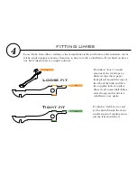
Page 9: ...tion 4 FITTING LIMBS Tape Sand Tape If a limb is loose a small amount of electrical tape or whatever tape that is paper thin placed around the tops of the tabs of the limb and then the top plate locks it in place when it s all re assembled takes away the gap and results in a solid frame once again If a limb is tight as in can t get the limb through the slot a small amount of sanding across just th...

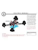
Page 10: ...st to ensure proper fit Some light sanding may be neces sary but it should be a tight fit so be patient with this step Be careful to note the direc tion of the ESC and the FC Be sure they are all aligned correctly M3 x 10 Screw x 4 5 Main Body Assembly M3 x 10 Screw WARNING Do not use standoff screws to force the top or bottom plates on to the limb The limbs should fit very snug but press on the p...

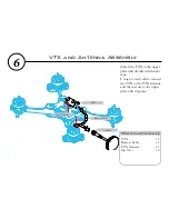
Page 11: ...h double sided sticky tape Using a remote cable connect the VTX to the VTX antenna and then secure to the upper plate with 2 zip ties VTX Remote Cable VTX Antenna Zip Ties x 1 x 1 x 1 x 2 5 6 7 8 A B C Zip Tie Holes 6 VTX and Antenna Assembly VTX Antenna Remote Cable ...

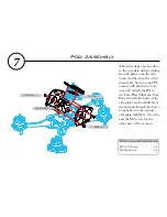
Page 12: ...camera with 2mm screws to one side Attach the RX to the Cam Plate Slide the Cam Plate through the holes of the side plates and carefully feed the antenna through the holes as well Secure the second side plate with M3 x 10 screws and the M2 screw for the other side of the camera M3 x 10 Screw M3 Lock nut x 4 x 4 5 6 7 8 A B C FPV Camera M2 Screw Receiver M3 Screw 7 Pod Assembly ...

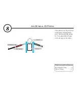
Page 13: ... can be protected using plastic tubing held in place with heat shrink tubing 1 4 should suffice Finish with end caps for the tubes Heat Shrink Tubing Plastic Tubing x 4 x 4 Heat Shrink Tubing Plastic tubing Receiver Antenna 8 Antenna Option ...

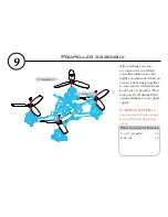
Page 14: ...ghly recommended that you secure your racing propellers to your motors with lock nuts Lock nuts are prerable Prop nuts may fly off during flight causing damage to your quad copter WARNING NEVER test your motors with the propel lers on Physical harm may occur 5 or 6 propeller Lock nut x 4 x 4 9 Propeller Assembly Propeller Lock nut ...

Page 15: ... 8 A B C D Now you ve completed your build Be sure to research your particular equipment and be sure it is 100 opera tional before attempting to fly WARNING NEVER test your motors with the propel lers on 10 Ready to Fly ...

Page 16: ...NOTES ...

Reviews: